Connecting wired sensors – Winland Electronics EA800-ip User Manual
Page 25
Installation
D-011-0152
25
■
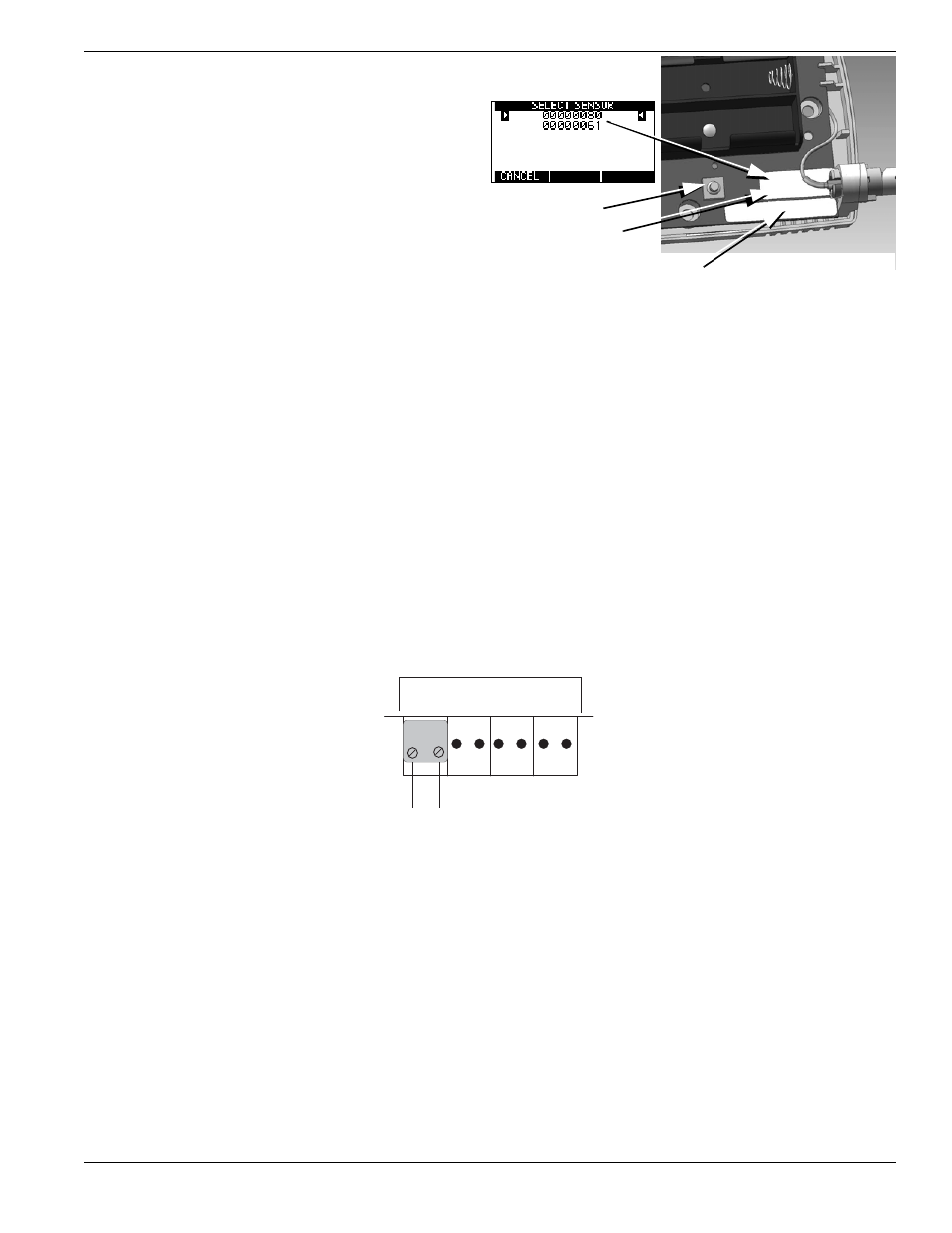
When a sensor is detected, confirm that the ID
number shown matches the ID number on the
sensor’s label.
■
If the sensors can communicate with the EA800,
their IDs appear in the list as shown in the
example at right. Do not permanently install the
sensors that appear in the list until you verify
their signal strength (page 56) when you
program the wireless sensors in the system later
in the installation process.
■
If the list of number(s) on the screen does not
contain the number found on the sensor's orange
label, press F1 (CANCEL) to continue the
search process.
Note:
Press the Reset Button on the sensor to
restart the search process if necessary.
After the console has identified each wireless sensor and you have programmed it, temporarily mount it in its
desired location using tape. This allows the sensor to be relocated if necessary in order to obtain good signal
strength
Connecting Wired Sensors
1.
Make certain the sensor's wiring is passed through the opening in the mounting plate.
2.
Remove the pluggable terminal block from the correct input connector header by pulling it up and off of the
circuit board header connector.
3.
Strip the ends of each of the sensor's wires 1/4" (6.4 mm). If stranded, twist strands after stripping.
4.
Insert the stripped wire ends into screw terminals of the terminal block. See Figures 10-12.
Figure 10 EA800 Console Wired Temperature, Dry Contact, and WaterBug
®
Sensor Connections (Not Polarity-Sensitive)
5.
Secure the connections using the setscrews on the terminal block. Check the connection by lightly pulling on
each connection.
RESET BUTTON
SENSOR MODEL NO.
(Example: EA-WTS = Wireless Temperature Sensor)
MAC Address Label
Figure 9 Wireless Sensor IDs and MAC Address Location
J6
Input 1 Input 2 Input 3 Input 4
+
(-) +
(-)
+
(-)
+
(-)