Specifications, Pecifications – Pulsafeeder MPC User Manual
Page 47
13. Specifications
Turndown: Up to 1000:1 with a steady state accuracy of +/- 2 % (added
to pump accuracy rating)
3:1 with a steady state accuracy of +/- 1 % (added to pump accuracy
rating)
Operation mode: AC motor speed control with speed and stroke length
feedback
Manual stroke length control
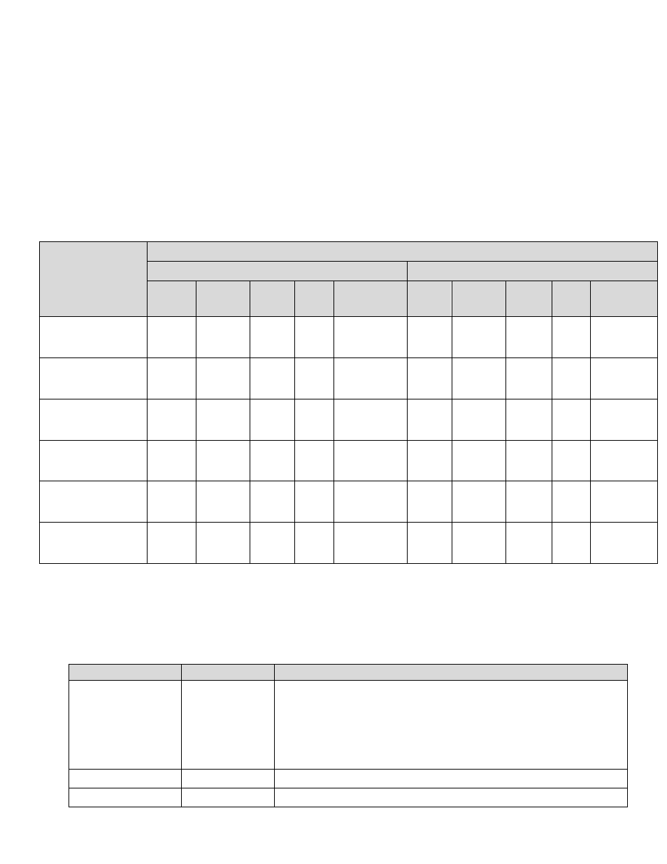
Power
Requirements
Recommended Minimum Wiring and Circuit Breaker
115 VAC Operation
230 VAC Operation
Actual
Draw
Circuit
Breaker
Wire
Size
Wire
Size
Safety
Approvals
1
Actual
Draw
Circuit
Breaker
Wire
Size
Wire
Size
Safety
Approvals
1
MPC and 0.25
Hp motor
7.0 A
10 A
14
AWG
2.5
mm
2
UL, CUL,
CE
3.5 A
10 A
14
AWG
2.5
mm
2
UL, CUL,
CE
MPC and 0.33
Hp motor
7.0 A
10 A
14
AWG
2.5
mm
2
UL, CUL,
CE
3.5 A
10 A
14
AWG
2.5
mm
2
UL, CUL,
CE
MPC and 0.5 Hp
motor
9.4 A
15 A
14
AWG
2.5
mm
2
UL, CUL,
CE
5.2 A
10 A
14
AWG
2.5
mm
2
UL, CUL,
CE
MPC and 0.75
Hp motor
16.8 A
25 A
12
AWG
4.0
mm
2
UL, CUL
9.4 A
15 A
14
AWG
2.5
mm
2
UL, CUL
MPC and 1.0 Hp
motor
16.8 A
25 A
12
AWG
4.0
mm
2
UL, CUL
9.4 A
15 A
14
AWG
2.5
mm
2
UL, CUL
MPC and 1.5 Hp
motor
24.2 A
35 A
10
AWG
6.0
mm
2
UL, CUL
12.2
A
20 A
14
AWG
2.5
mm
2
UL, CUL
NOTE: AC drive capacitors will cause in-rush current demand when power is first
applied to the unit. Applicable national and local electrical codes take precedence
over recommendations in these tables.
Control Inputs
Wiring
Specification / Description
Analog In #1
J11 pins 4-6
4-20mA control signal
Max current 30mA; Input resistance 200 Ohm
Internally protected with resetable fuse
Minimum signal accepted = 2.4 mA
Maximum signal accepted = 24 mA
Analog In #2
J11 pins 5-6
Not presently available – future release
Digital In #1
J11 pins 1-3
User to provide dry-contact input *