5 check wiring and close access cover, 6 confirm correct incoming power, Check wiring and close access cover – Pulsafeeder MPC User Manual
Page 25: Confirm correct incoming power
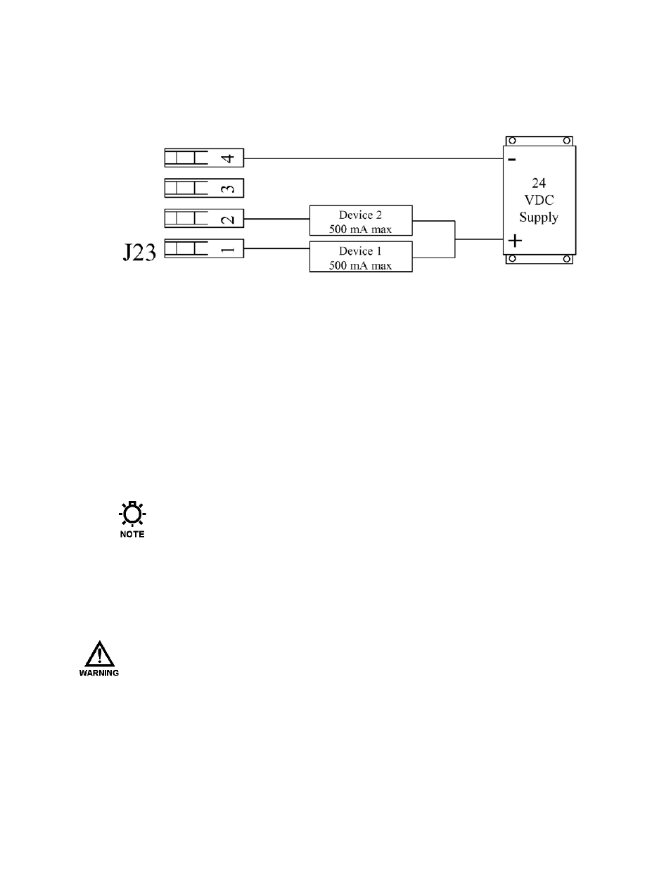
Digital output signals can drive devices such as relays or indicator lamps. 24 VDC
power must be supplied from an external source. Each output has a maximum current
capability of 500 mA. Maximum voltage capability of these circuits is 40 VDC (see the
Specifications Section, for more information).
Figure 5 – Sample Digital Output Connections
8.5 Check Wiring and Close Access Cover
Double-check all of your electrical connections. Pay attention to polarity
of all inputs and outputs – both low and extra-low voltage. Additionally,
insure that all terminals are clamping onto the bare conductor, not on its
insulation. Ensure that wires will not be trapped or pinched when front
cover is replaced and secured. Ensure that excess insulation is not
removed from the wires, as this can lead to poor connections or faulty
operation.
Replace the main access cover and secure the 10 bolts.
Use a nut driver to tighten the retaining bolts evenly to 35 in-lbs
(4.0 Nm). Failure to do so may cause the cover to leak and void the
warranty.
8.6 Confirm Correct Incoming Power
W
ITHOUT PRIOR OPERATING KNOWLEDGE
,
IT IS IMPOSSIBLE TO TELL IF THE
PUMP MOTOR WILL RUN WHEN POWER IS APPLIED TO THE
MPC.
Y
OU ARE
RESPONSIBLE FOR TAKING THE NECESSARY STEPS TO ENSURE THAT ALL
ASPECTS OF SAFETY HAVE BEEN CONSIDERED
(
E
.
G
.,
ELECTRICAL
,
HYDRAULIC
,
ETC
.).
Clear all lockout tag out controls. Turn on power at the mains or
distribution panel. If the MPC's incoming power is connected correctly,
the backlighting on the MPC's display will illuminate (depending on
lighting conditions, it may be necessary to shade the display to confirm
illumination). If the display is not illuminated, first check the line voltage