Lyntec RPC User Manual
Page 8
139-0498-01.8
8
Chapter One--Overview
Additional Boards Overview
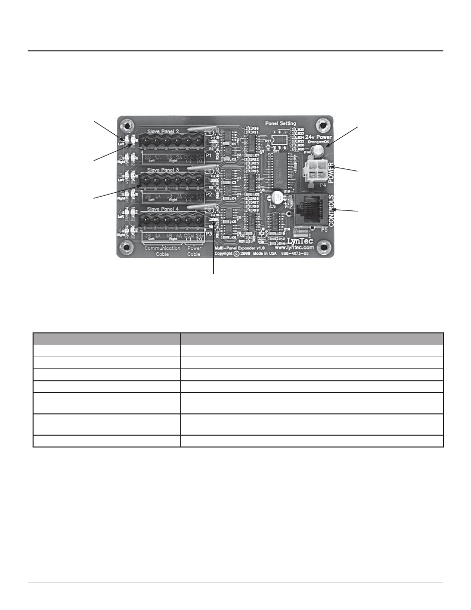
Figure 1-3: Multi-Panel Expander Board
Figure 1–3 shows the parts of the additional slave
board. A brief description of each part follows in
Table 1–3.
A
B
C
D
E
F
G
Component
Description
A. Power LED
The power LED is always orange when the board is receiving power.
B. Power Input
Provides power to control busses on panels two, three and four.
C. Control Input
Receives control signal from control board.
D. Control Bus Indicator
Indicates that the control busses on panel two, three or four have power.
E. Data transmission indicator
Indicates that the Multi-Panel expander board is transmitting data to a
particular control bus (example: panel 2 left).
F. Data reception indicator.
Indicates that the Multi-Panel Expander Board is receiving data from a particular
control bus (example: panel 2 left)
G. Expansion Ports
Connects the MPE board to control busses on panels two, three and four.
Table 1-3: Parts of the Multi-Panel Expander Board