Tcp/ip dmx rs-232 – Lyntec RPC User Manual
Page 17
139-0498-01.17
17
Chapter Four--Wiring
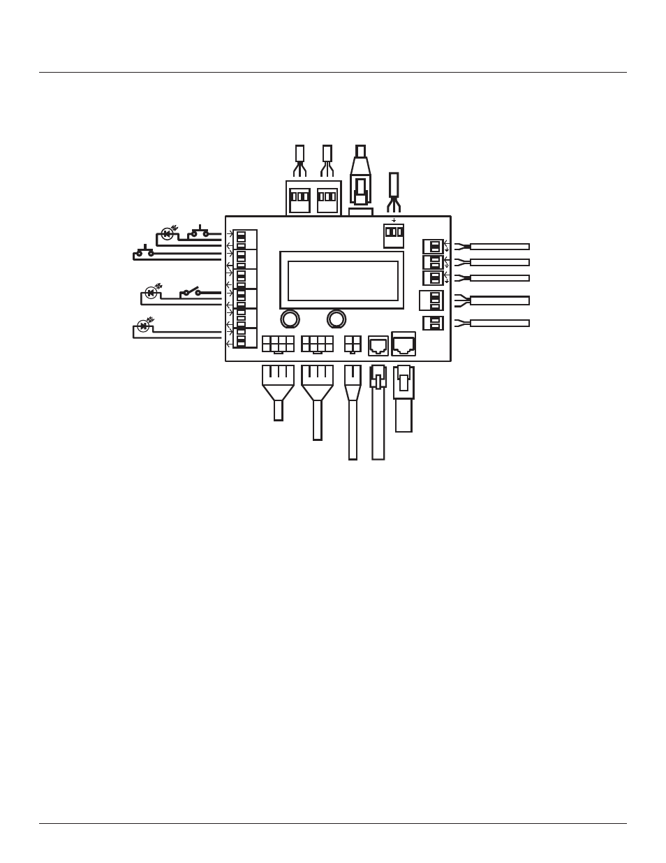
Figure 4-5: Control Wiring
Install and connect a standard Cat. 5e cable from the facility
network to the Controller Ethernet port.
If DMX-512 is being used to control the panel, install and
connect a shielded pair cable from the DMX source to the
Controller DMX Input three-position spring-clamp header.
Terminate common, DMX– and DMX+ from left to right in the
header. Follow the same wiring guide for the DMX Thru header.
If RS-232 is being used to control the panel, install and connect
a shielded pair cable from the RS-232 source to the Controller
RS-232 three-position spring-clamp header. Terminate receive,
ground and transmit from left to right in the header.
Analog Inputs for
Control Functions
Audio Sensing Timer
24VDC source for
external device
RJ-45 8P8C Flat Cable
to Controls Port on MPE
RJ-25 6P6C Flat Cable
to I/O Port on I/O Card
24 VDC from P/S Unit
Transducer Input Lines
Right Breaker
Control Bus
Left Breaker
Control Bus
Light Sensor for
Zone Control
24 VDC LED
Indicator
Maintained
Contact Switch
Momentary
OFF
24 VDC LED
Indicator
Momentary ON
Contact Switch
Ethernet Cable to
Facility Network
TCP/IP
DMX
RS-232
1
2
3
4
5
6
RS-232
1
2
3
+
–
MPE
I/O
Left Bus
Right Bus
RX
TX
Ethernet
Cat 5e
Power
–
–
+
+
c
c
c
DMX-512 Control
Input
Thru
Analog
Inputs
IN
24V
OUT
ON
OFF
Digital I/O
+
–