Lyntec RPC User Manual
Page 16
139-0498-0116
Chapter Four--Wiring
16
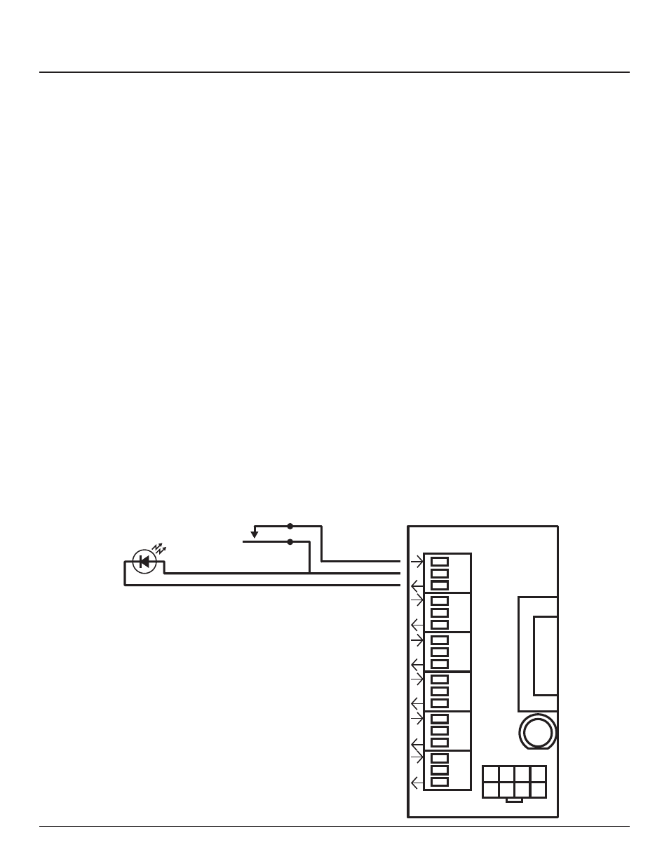
Emergency Shutdown Wiring:
To connect your fi re alarm or emergency management system
to the RPC, follow these steps.
1. From the fi re alarm unit or latching Emergency Shutoff
switch, wire the Normally Open (NO) contacts to the IN and
24V positions of Digital I/O Port #1 on the Controller.
2. If a remote status indicator is used, ensure that the positive
terminal is wired to the 24V position and the negative
terminal is wired to the OUT position of Digital I/O Port #1.
3. When the Normally Open contacts are closed, the status
indicator should immediately light and all breakers that
have been selected for E. Shutoff should cycle to OFF.
4. When the contacts are released, the status indicator should
extinguish and all breakers that were ON when E. Shutoff
was activated should return to the ON state.
See Chapter 5 to confi gure the software for emergency
shutdown.
Figure 4-4: Emergency shutdown
wiring
Normally Open
Fire Alarm Contacts
24 VDC LED
Status Indicator
1
2
3
4
5
6
Left Bus
IN
24V
OUT
Digital I/O
OFF