Lyntec RPC User Manual
Page 14
139-0498-0114
Chapter Four--Wiring
14
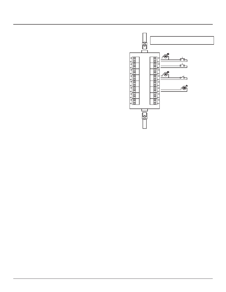
Figure 4-3: Digital I/O Remote Switch
and Sensor Wiring
Momentary OFF
Contact Switch
Maintained
Contact Switch
Light Sensor for
Zone Control
RJ-25 6P6C Flat Cable
to next I/O Board
Momentary ON
Contact Switch
RJ-25 6P6C Flat Cable
to I/O Port on Controller
24 VDC LED
Indicator
24 VDC LED
Indicator
Switches or sensors being used to control either sequenced
or grouped zones are to be connected to the Digital I/O three-
position spring-clamp headers. Each header can accommodate
one input device (switch, sensor, relay) and one output device
(indicator) maximum.
The center terminal of each Digital I/O header is used as a 24VDC
source. The input terminal is triggered when connected through
a remote device to the 24VDC source. The output terminal
activates a remote device by pulling down from 24VDC to 0VDC
and creating current fl ow.
To assign both an On and Off function for one zone would
require two input terminals and occupy two I/O headers. Six (6)
Digital I/O headers are located on the left side of the Controller
board. If more connections are required for multiple zone
control, additional I/O Expander boards can be added. Each
I/O Expander board provides an additional 16 headers for a
maximum total of 38 input control sources and output indicators.
1
2
3
4
5
6
7
8
10
11
12
13
14
15
16
I/O Port
I/O Port
9
OUT
24V
IN