Lyntec RPC User Manual
Page 19
139-0498-01.19
19
Chapter Four--Wiring
SS-2PL and SS-2LRP Locking Switch
Sets
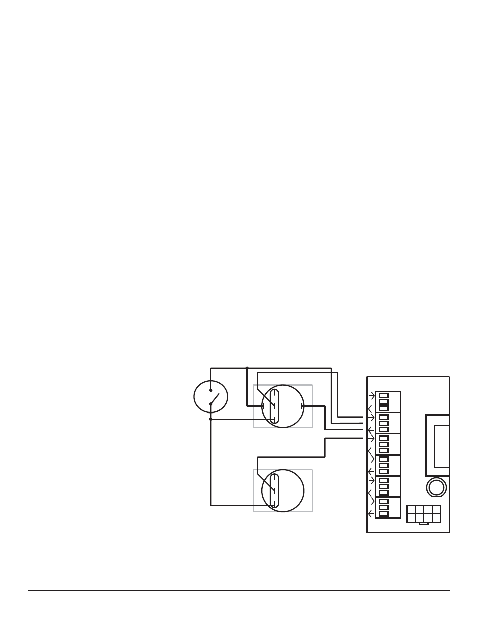
Figure 4-7
To confi gure the Digital I/O port and link it to a zone see
Chapter 5.
Using a standard LynTec SS-2PL or SS-2 LRP Switch Set with
illuminated ON switch. See Figure 4-7
1. Wire the ON switch to Digital I/O port 2 on the left edge of
the Controller board as follows:
i. Connect the 24VDC Common (center terminal of the I/O
port) to the + pin of the ON switch.
ii. Connect the + pin on the on switch to the 1 pin on the
lock.
iii. Connect the Input terminal (arrow pointing towards
header) to the NO pin of the ON switch.
iv. Connect the Output terminal (arrow pointing away from
header) to the – pin of the ON switch.
v. Connect the C pin on the ON switch to the 3 pin on the
lock.
2. Wire the OFF switch to Digital I/O port 3 on the left edge of
the Controller board as follows:
iii. Connect the 3 pin on the lock to the C pin on the OFF
switch.
iv. Connect the Input terminal to the NO pin of the OFF
switch
1
3
Left Bus
IN
24V
OUT
ON
C
LOCK
Digital I/O
NO
C
NC
+
–
NO
NC
ON
OFF
1
2
3
4
5
6