Lyntec, Quick start guide, Rpc quickstart guide – Lyntec RPC User Manual
Page 40
139-0498-01.40
Appendix A
40
RPC Quickstart Guide
LynTec
RPC
Quick Start Guide
1
Mak
e sure that the panel(s) ha
ve
been wired by a quali
fi ed
electrician
and that there is power to the panel(s).
Con
fi
rm that RPS (sla
ve) panels
are connected to the master as indicated in the “RPC to RPS Wiring Instructions” bulletin.
2
Con
fi
rm that the electrician has
connected the 15A break
er in the
master panel (position 21) to the power supply in the lower sidecar
.
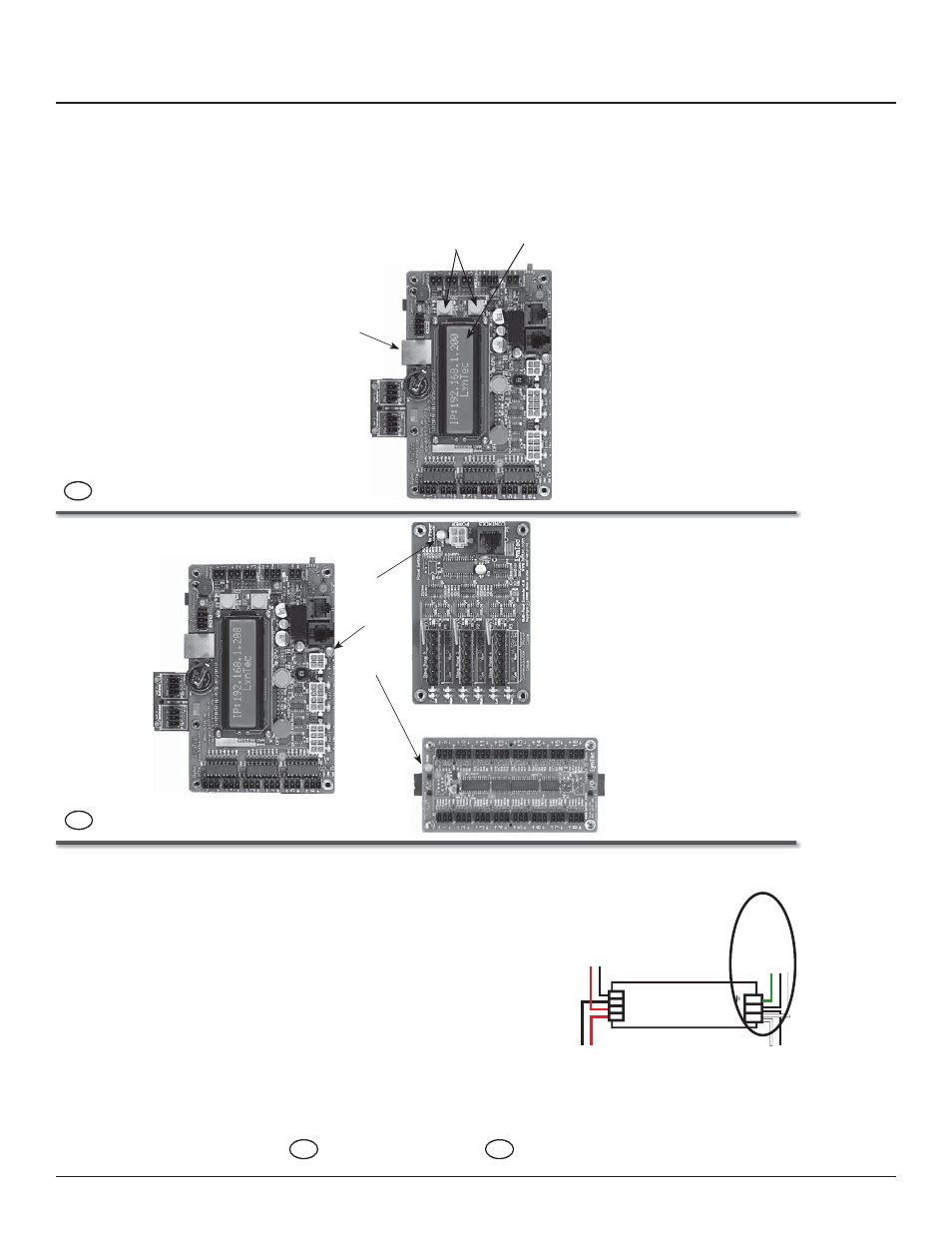
3
Once the 15A break
er is connected
and switched on, con
fi
rm that the
or
ange power LEDs on each circuit
board are lit.
Control Board
I/O Expander Board
Multi-Panel Expander Board
POWER LEDS
If LEDs do not light, check chapter 4 of the RPC manual to see that circuit boards are connected properly
.
4
Connect a computer to the control board using a CA
T5 crosso
ver
cable OR connect the RPC to y
our
network.
If connecting via a crossover cable:
With a computer directly connected to the RPC through the Ethernet port, change the computer
’s
IP
address manually so it is in the same default IP subnet that the RPC uses: 192.168.1. The default IP address of the RPC is 192.168.1.250.
Ethernet Port
Yellow Buttons
LCD
Screen
If connecting via a network:
Connect the RPC to the network via the Ethernet port. Push the upper yellow button twice or until the IP address appears on the L
CD screen.
P
anel Neut
ra
l Bus
P
anel Ground Bar
P
o
w
e
r Supply DC –
Controller Ca
b
le
Controller Ca
b
le
P
o
w
e
r Supply DC +
N L
+ + – –
T
ransducer Neut
ra
l
T
ransducer Load
15A Breaker
139-0522-00 RPC Quicksheet