Additional control options – Lyntec RPC User Manual
Page 12
139-0498-0112
Chapter Four--Wiring
12
6. Connect the green 14 AWG wire from the ground terminal of
the Power Supply unit to the ground bar attached directly to
the panel interior (DO NOT attach to the isolated technical
ground in the sidecar).
7. Install and connect all load, neutral and Isolated Technical
Ground feeds to circuits.
8. Ensure that all bolts and lug connections in the panel
are tight. Check both sides of the main breaker, the bars
connecting the busses to the main and all breaker retaining
bolts.
9. Check the cable connections at the top of the breaker control
busses to ensure the connectors are properly seated.
10. Replace the dead front pan and cover with door.
ADDITIONAL CONTROL
OPTIONS
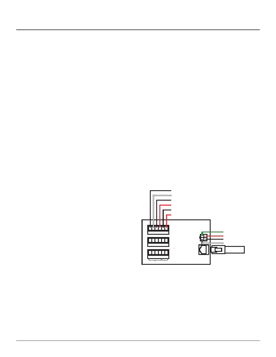
Figure 4-1: Multi Panel Expander
Additional circuit boards may be used to add additional panels or
I/O inputs.
1. If RPS Slave panels are being used in conjunction with an
RPC Master panel, install and connect one 18 AWG six (6)
conductor (Belden 27600 A or equivalent) or two 18-24 AWG
twisted pairs for data and one 16-18 AWG for power per RPS
unit. Terminate the Left Bus B, Left Bus A, Right Bus B, Right
Bus A, Common (–) and 24VDC (+) in the screw-terminal
header for that RPS (Slave Panel 2 – 4) from left to right.
Slave Panel 2
Slave Panel 3
Slave Panel 4
Controls
Power
Communication Power