Lyntec, Contact closure wiring instructions – Lyntec RPC User Manual
Page 42
139-0498-01.42
Appendix A
42
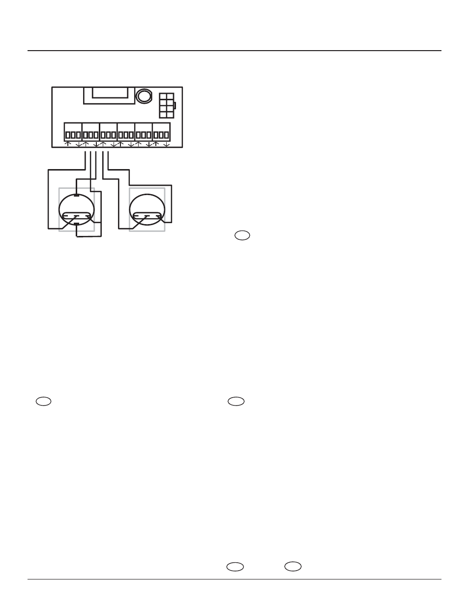
RPC Contact Closure Wiring Instructions
1
2
3
4
5
6
Left Bus
IN
24V
OUT
Digital I/O
NO
C
NC
+
–
NO
C
NC
ON
OFF
OFF
LynTec
RPC
Contact Closure Wiring Instructions
1
Con
fi
rm that RPS (sla
ve) panels are
properly connected to the master as indicated in the “RPC to RPS Wiring Instructions” bulletin.
2
Complete all the steps in the “RPC Quick Start Guide”
.
Using a standard L
ynT
ec S
S-2 S
witch
Set with illuminated ON switch. (F
or
other types of switches, consult CH 4 of the instruction bulletin for wiring diagr
ams.)
3
Wire the ON switch to a digital I/O port on the left edge of the Controller board as follows:
A.
Connect the 24VDC Common (center terminal of the I/O port) to the C pin of the ON switch.
B
.
Connect the Input terminal (arrow pointing tow
ards header)
to the NO pin of the ON switch.
C.
Connect the Output terminal (arrow pointing aw
ay
from
header) to the – pin of the ON switch.
D
.
Connect a jumper between the C pin and the + pin of the ON switch.
4
Wire the OFF switch to a digital I/O port on the left edge of the Controller board as follows:
A.
Connect the 24VDC Common terminal to the C pin of the OFF switch.
B
.
Connect the Input terminal to the NO pin of the OFF switch
Note: If using emergency override features,
fi
re alarm contact closures
must be wired into port 1.
5
On the RPC web page, go to
the contact closure page. (SETUP
==>
CONT
ACT CL
OSURES)