Lyntec RPC User Manual
Page 7
139-0498-01.7
7
Chapter One--Overview
Table 1-1: Parts of the RPC Controller
Component
Description
N. Reset Button
Resets the controller.
O. MPE Port
Connects the Multi Panel Expander Board (for use with up to 3 slave panels)
P. I/O Board Port
Connects additional I/O boards to the controller. Up to two boards can be added for a
total of 38 contact closure inputs.
Q. Power Led
Illuminates when the controller is receiving power.
R. Power Supply Input
Connects the controller to the power supply.
S. CPU LED
CPU Heartbeat
T. Right RX LED
Flashes when the controller is receiving data from the right control bus.
U. Right Control Bus Port
Connects the controller to the right control bus.
V. Right TX LED
Flashes when the controller is transmitting data to the right control bus.
W. Left RX LED
Flashes when the controller is receiving data from the left control bus.
X. Left Control Bus Port
Connects the controller to the right control bus.
Y. Left TX LED
Flashes when the controller is transmitting data to the right control bus.
Z. Digital I/O Ports
Contact closure input, indicator output, and 24VDC common
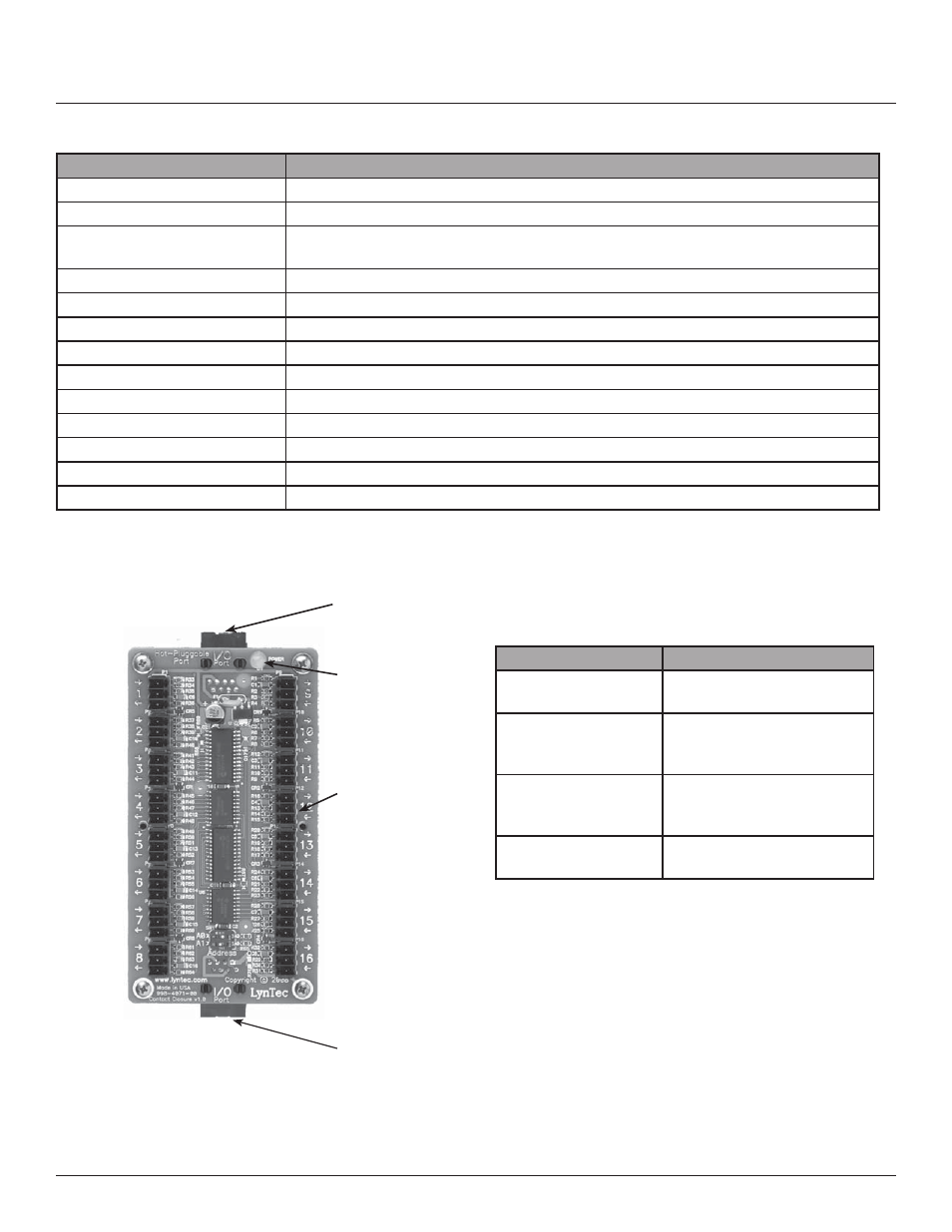
Figure 1-2: I/O Expander Board
Figure 1–2 shows the parts of the I/O Board. A
brief description of each part follows in Table 1–2.
A
B
C
Component
Description
A. I/O Control Port
Connects the board to the
controller.
B. Power LED
The power LED is always on
when the board is receiving
power.
C. Digital I/O Headers
Allows the panel to be
controlled by contact closure
devices.
D. I/O Control Port
Thru
Connects to an additional I/O
expander board.
Table 1-2: Parts of the I/O Board
Controller Overview
D