Wx y – Lyntec RPC User Manual
Page 6
139-0498-01.6
6
Chapter One--Overview
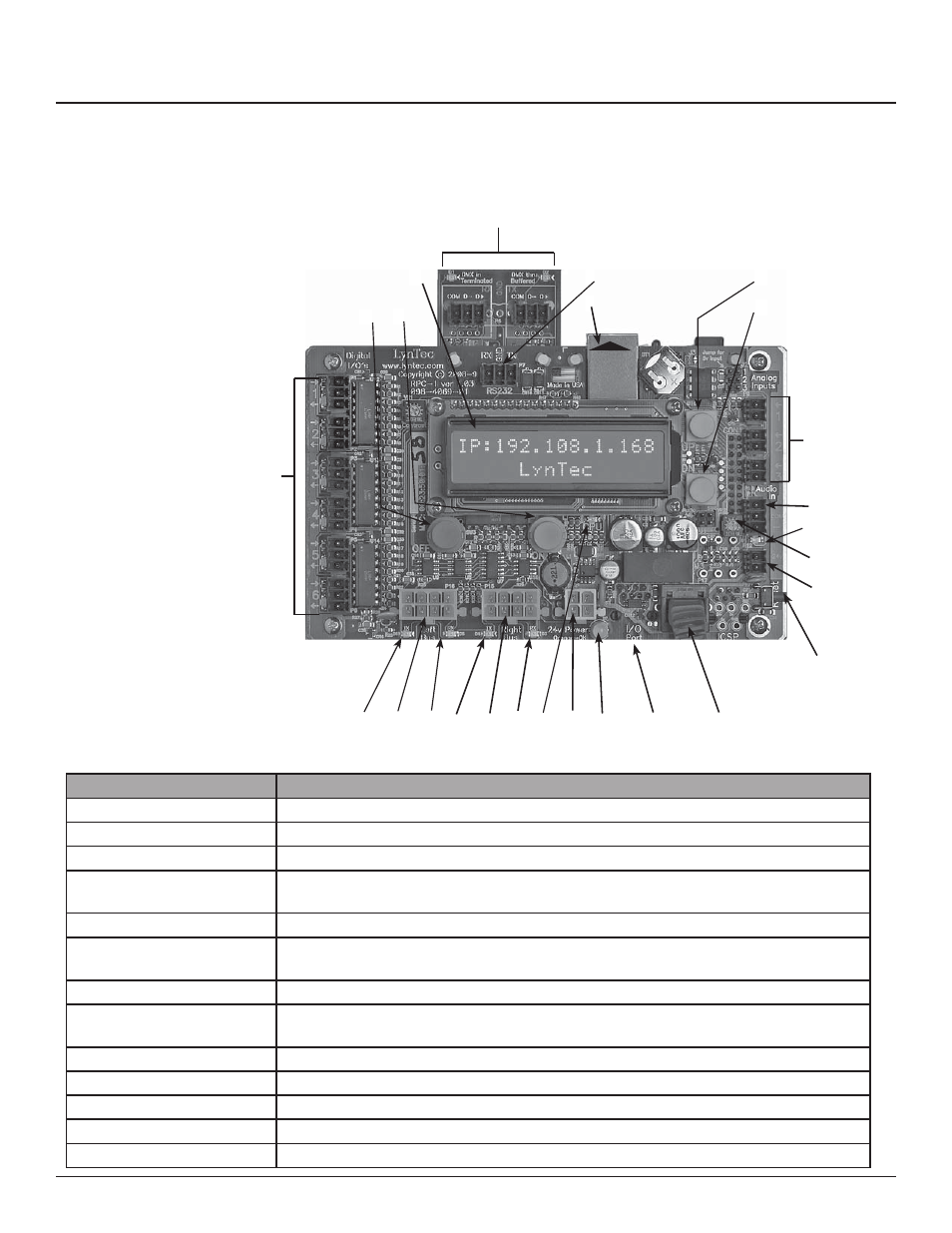
Controller overview
Figure 1–1 shows the parts of the RPC controller.
A brief description of each part follows in Table
1–1.
Figure 1-1: RPC Controller
A B
C
D
E
F
G
H
I
J
K
L
M
N
O
P
Q
R
S
T
U
V
A. Off Button (Red)
B. On Button (Green)
C. LCD Screen
D. DMX Input and Thru
E. RS-232
Port
F. Ethernet
Port
G. Menu Up Button
H. Menu Down Button
I. Analog
Inputs
J. AST
Input
K. Audio Signal Indicator
L. AST Sensitivity Potentiometer
M. Auxiliary Power Output
N. Reset Button
O. MPE Board Port
P. I/O Board Port
Q. Power LED
R. Power Supply Input
S. CPU
LED
T. Right RX LED
U. Right Control Bus Port
V. Right
TX
LED
W. Left RX LED
X. Left Control Bus Port
Y. Left
TX
LED
Z. Digital I/O Ports
Table 1-1: Parts of the RPC Controller
Component
Description
A. OFF Button
Turns all breakers off
B. ON Button
Turns all breakers on
C. LCD Screen
Screen shows the IP address, time and setup information.
D. DMX Input and Thru
Allow the panel to be directed by a secondary DMX controller. When DMX is enabled, the
control page is disabled.
E. RS-232 Port
Control Port for secondary controller such as AMX or Crestron.
F. Ethernet Port
Connects the panel to a computer or network for initial setup or long-term operation us-
ing the built-in web interface.
G. Menu Up Button (yellow)
Scrolls the screen up.
H. Menu Down Button (yel-
low)
Scrolls the screen down.
I. Analog Inputs
Additional analog inputs to connect voltage/current monitors or light sensors.
J. AST Input
Connects to the Audio Sensing Timer
K. Audio Signal Indicator
Flashes when audio signal is present.
L. AST Sensitivity Pot
Sets the sensitivity of the Audio Sensing Timer
M. Auxiliary Power Output
Auxiliary 24V power for accessories.
Controller Overview
W
X
Y
V
A B
C
E
F
G
H
V
V
V
V
V
V
V
V
V
V
V
V
TCP/IP
Network
connect
Z