Lyntec RPC User Manual
Page 13
139-0498-01.13
13
Chapter Four--Wiring
2. At the RPS Slave panels, strip the cable sheath back
approximately 20 inches. Cut the conductors for Left Bus
B, Left Bus A, – and + down to approximately 4 inches and
terminate them in the Left Bus screw-terminal header from
left to right. Terminate the remaining two conductors in
the Right Bus B and Right Bus A positions of the Right Bus
screw-terminal header.
3. Using two cut lengths of 18 AWG wire, install jumpers from
Left Bus – and + to Right Bus – and +. Right Bus will not
operate without these jumpers installed to provide 24VDC
power and common.
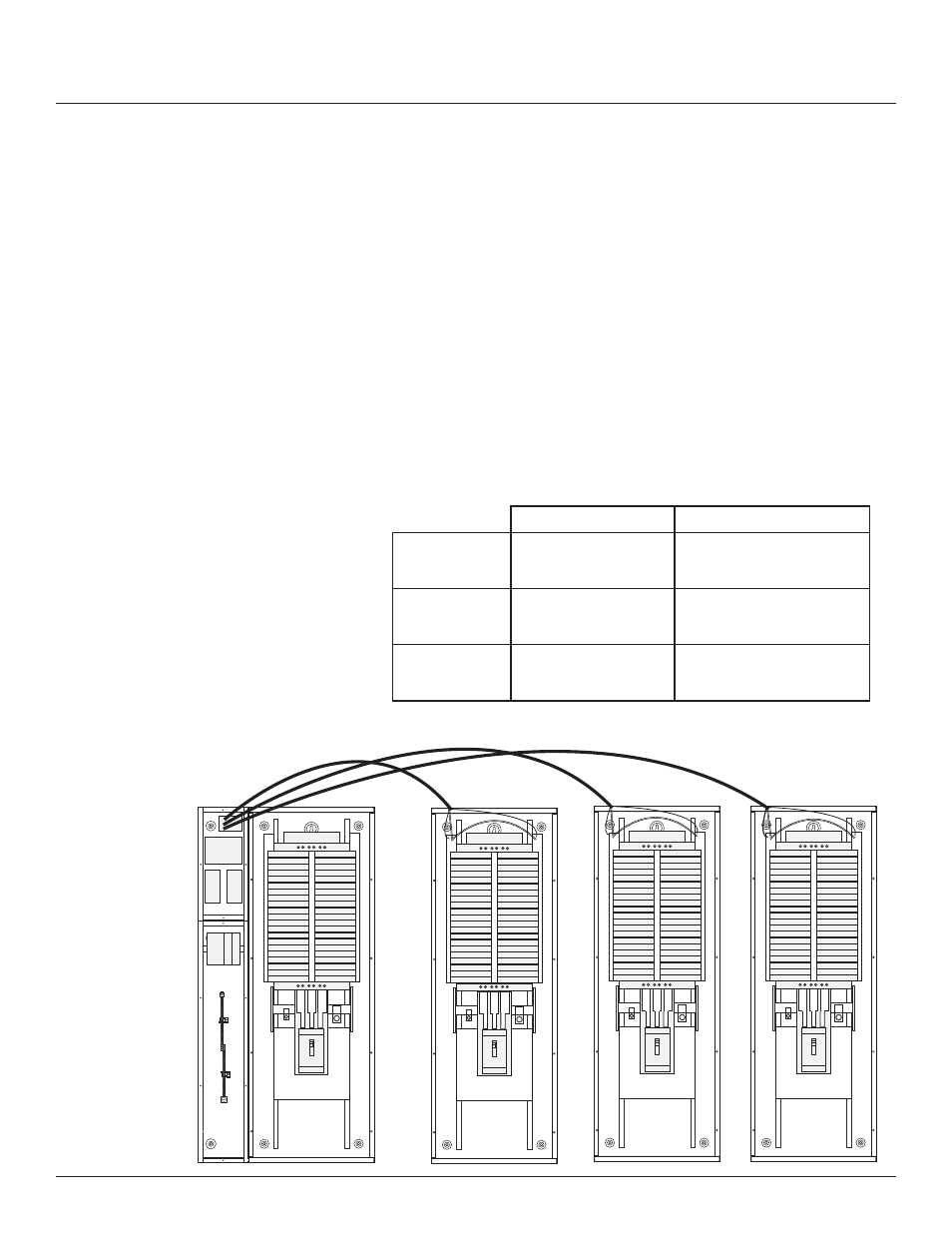
4. Set the slave address selectors as follows:
Table 4-2
Left Control Bus
Right Control Bus
Panel #2
2
3
Panel #3
4
5
Panel #4
6
7
Master Panel
Slave Panel 2
Slave Panel 3 Slave Panel 4