1. cutaway of vibrating wire sensor, 1. avw200 measurement inputs – Campbell Scientific AVW200-series Vibrating Wire Interfaces User Manual
Page 16
AVW200-series 2-Channel Vibrating Wire Spectrum Analyzer Modules
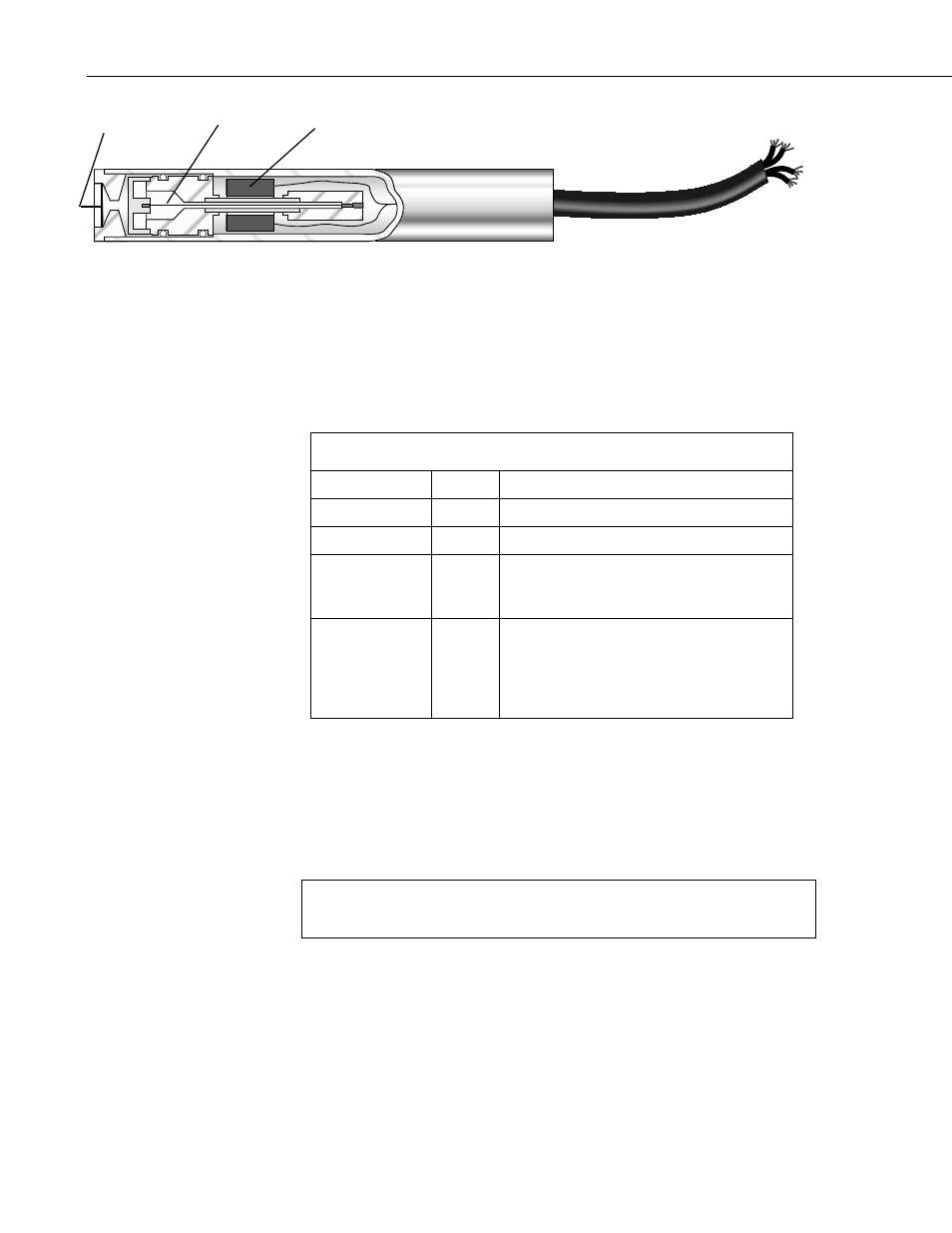
FIGURE 2-1. Cutaway of Vibrating Wire Sensor
There are three user-determined inputs to the AVW200 measurement process
and five outputs from the measurement process. The input parameters control
the excitation frequency range (BeginFreq and EndFreq) and the excitation
amplitude (ExVolt); see TABLE 2-1. The frequency range supported spans
from 100 Hz to 6500 Hz.
TABLE 2-1. AVW200 Measurement Inputs
Input
Units
Description
BeginFreq
Hz
Minimum excitation and analysis frequency
EndFreq
Hz
Maximum excitation and analysis frequency
ExVolt
Unitless Excitation voltage
1: 5 Volts peak to peak
2: 12 Volts peak to peak
Therm50_60Hz
(see Section 2.2)
Unitless Thermistor measurement parameter
0:
No thermistor
measurement
_60Hz
Use 60 Hz noise rejection
_50Hz:
Use 50 Hz noise rejection
The measurement outputs are resonant frequency, response amplitude, signal-
to-noise ratio, noise frequency, and decay ratio; see TABLE 2-2. The raw
frequency measurement output of the AVW200 is in Hertz unlike our previous
interfaces, which output kHz
2
or 1/T
2
(where T is the period in milliseconds).
The Hertz output is converted to the appropriate units of measurement (e.g.,
pressure, strain, displacement) by using information provided on the sensor’s
calibration report.
Read more! You can find an example of converting Hertz to displacement
in Appendix A and an example program that converts Hertz to
displacement in Section 7.1.2.
Plucking/
Pickup Coil
Vibrating
Wire
Diaphragm
8