Step 9 programming the setpoints, Step 10 programming profile setup (optional) – Red Lion DLC User Manual
Page 9
9
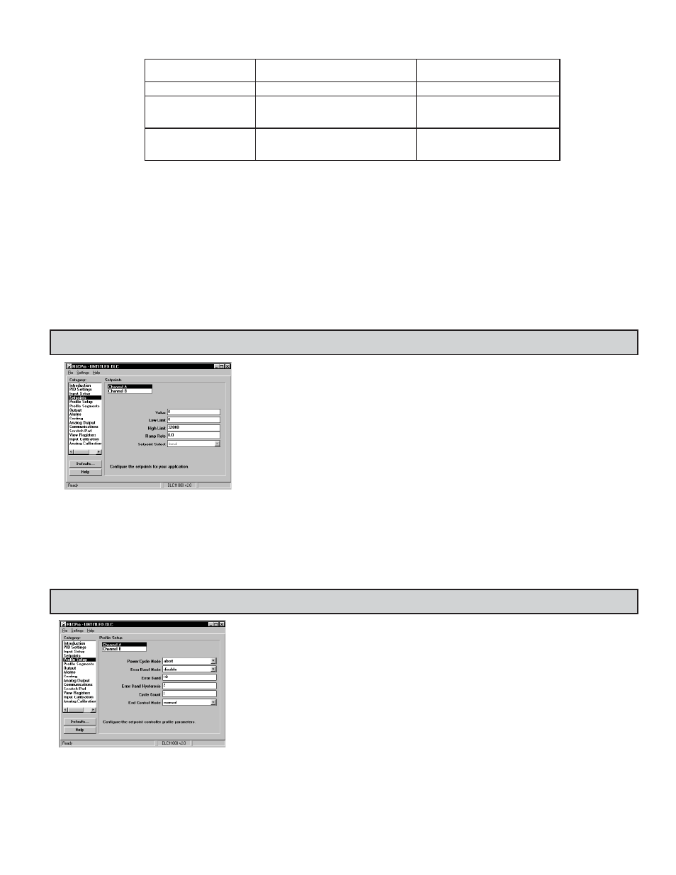
STEP 9 PROGRAMMING THE SETPOINTS
Setpoint (40002/40018): Enter the setpoint value. Deviation of Process Value (40001/40017) from
setpoint value can be viewed in the Setpoint Deviation register (40006/40022).
Low Limit (40108/40208); High Limit (40109/40209): The controller has programmable high and low
setpoint limit values to restrict the setting range of the setpoint. Set the limits so that the setpoint value
cannot be set outside the safe operating area of the process.
Ramp Rate (40110/40210): The setpoint ramp rate can reduce sudden shock to the process and reduce
overshoot on startup or after setpoint changes, by ramping the setpoint at a controlled rate. The ramp
rate is 0.1° for input types 0-11, 0.1
for input type 12, 0.01 for input type 13, and 0.1 unit for input
types 14-15 per minute. Writing a ‘0’ disables setpoint ramping. The Disable Setpoint Ramping register
(40042/40050) can also be used to disable ramping. The Setpoint Ramping In-Process register
(40043/40051) will be a ‘1’ during setpoint ramping. While ramping is enabled, the Ramping Setpoint
can be viewed in register (40045/40053). The Ramp Rate for CHB is not functional when it is assigned
as a Remote Setpoint Input.
Once the ramping setpoint reaches the target setpoint, the setpoint ramp rate disengages until the setpoint is changed again. If the ramp value is changed
during ramping, the new ramp rate takes effect. If the setpoint is ramping prior to starting Auto-Tune, the ramping is suspended during Auto-Tune and then
resumed afterward using the present Process value as a starting value. Deviation and band alarms are relative to the target setpoint, not the ramping setpoint. A
slow process may not track the programmed setpoint rate. At power-up, the ramping setpoint is initialized to the starting process value.
Remote/Local Setpoint Select (40046): Channel A setpoint mode can be switched between Local Setpoint operation and Remote Setpoint operation. The
Channel B input must be assigned as a remote setpoint (register 40198).
STEP 10 PROGRAMMING PROFILE SETUP (Optional)
Local/Remote Setpoint Transfer Mode (40199): When cycling from/to Local or Remote Setpoint (register 40046), the response of the controller can be
programmed to act in a variety of ways. The table summarizes the responses for Setpoint transfer options.
LOCAL/REMOTE SETPOINT
TRANSFER MODE
LOCAL TO REMOTE
REMOTE TO LOCAL
0 - Normal
Output may bump.
Output may bump.
1 - Auto
No output bump. Process error eliminated
at rate of integral action. Ramping disabled
during transfer.
No output bump. Process error
eliminated at rate of integral action.
Ramping disabled during transfer.
2 - Track
Output may bump.
Local Setpoint (40002) assumes value
of Remote Setpoint (tracks). No
output bump.
Note: In situations where an output bump may occur, the Setpoint ramp function can be used to reduce or eliminate bumping when switching Setpoint modes.
The setpoint ramp feature ramps the setpoint from the old setpoint to the new Setpoint.
Remote Setpoint Ratio Multiplier (40206): This value is used for channel B when it is assigned as a Remote Setpoint Input. The Ratio Multiplier applies to
all input types (0-15).
Remote Setpoint Bias Offset (40207): This value is used for channel B when it is assigned as a Remote Setpoint Input.
Scaling Points (40111-40114/40211-40214): Low and high scaling points are necessary to scale the controller for process voltage and current inputs. Each scaling
point has a coordinate pair of input and process value entries. The process value will be linear between and continue past the entries up to the limit of the input
range. Reverse acting measurement can be accomplished by reversing the Input or Process entries, but not both. (Do not reverse the input wires to change the
action.) To scale a 4-20 mA Input signal to provide process values of 0 to 100.00 (% in hundredths), the Input Low (40113/40213) and Input High (40114/40214)
values would be 4000 and 20000 (0.001 mA resolution), and the Process Low (40111/40211) and Process High (40112/40212) values would be 0 and 10000.
Process Decimal Point (Dec Pt) (40115/40215): The decimal point position is used to enable SFDLC display in desired engineering units for voltage and current
Process values. It is not used internally by the DLC.
Profile Power Cycle Mode (40321/40421): Upon controller power-on several profile operating modes
exist.
Stop: If the Profile was running when powered down, upon power-up, "Stop" places the profile into the
stop or off mode, regardless of the mode prior to the power-down. The active Setpoint is the setpoint
of the last segment that ran before power-down.
Abort: If the Profile status was running, paused, or in Error Delay when powered down, upon power-up,
"Abort" will place the controller in manual mode at 0% Output Power. The Setpoint and Ramp Rate
are the values they were prior to running the profile. If the Setpoint Controller was 'paused,' they will
be set to the values that they were at power-down.
Start: The Start power cycle mode causes the controller to automatically start the profile at Power-up.
This will occur if the unit was in manual or automatic control mode. During maintenance or at other
times when this action is not desired, the Profile Power Cycle mode should be changed appropriately.
Resume: At Power-up, Resume causes the profile to continue from the point and phase when power was
removed. If the unit was in ramp phase, the ramping setpoint will start ramping from the initial
process value at power-up.
Pause: Upon Power-up, the controller pauses and maintains control at the initial process value (on
power-up), at the phase where the controller was powered down. The user can then determine how to
proceed based on the process that is being controlled.