Pid tuning explanations, Auto-tune, Auto-tune code figure – Red Lion DLC User Manual
Page 19: Start auto-tune, Auto-tune progress, Pid adjustments, Process response extremes
19
AUTO-TUNE
Auto-Tune is a user-initiated function where the controller automatically determines the
Proportional Band, Integral Time, Derivative Time, Digital Filter, Control Ouput Dampening
Time, and Relative Gain (Heat/Cool) values based upon the process characteristics. The
Auto-Tune operation cycles the controlling output(s) at a control point three-quarters of the
distance between the present process value and the setpoint. The nature of these oscillations
determines the settings for the controller’s parameters.
Prior to initiating Auto-Tune, it is important that the controller and system be first tested.
(This can be accomplished in On/Off Control or Manual Control Mode.) If there is a wiring,
system or controller problem, Auto-Tune may give incorrect tuning or may never finish.
Auto-Tune may be initiated at start-up, from setpoint or at any other process point. However,
insure normal process conditions (example: minimize unusual external load disturbances) as
they will have an effect on the PID calculations. Auto-Tune cannot be initiated while running
a profile.
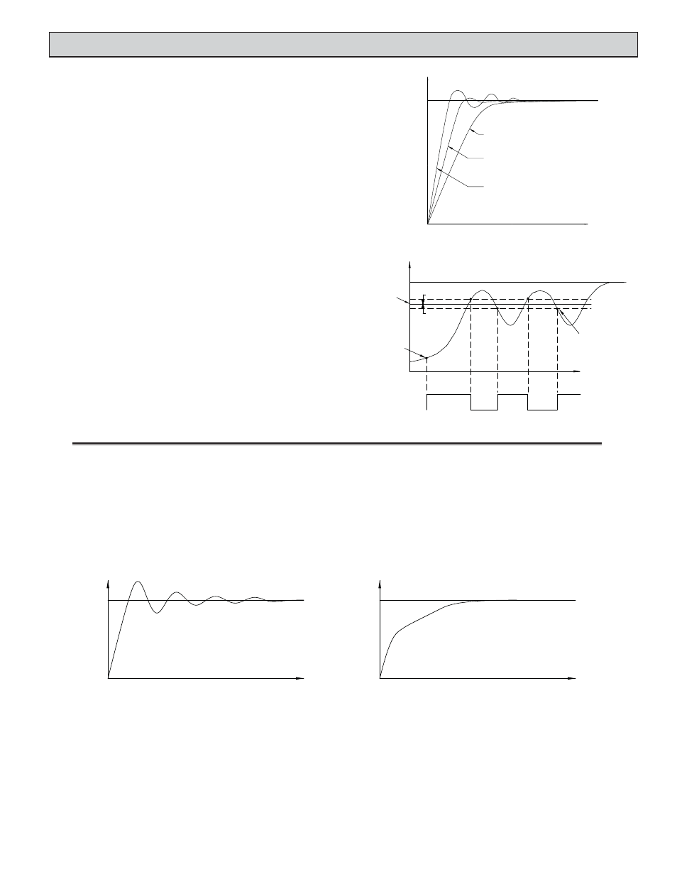
TIME
INPUT
TYPICAL RESPONSE CURVES WITH
AUTO-TUNE CODES 0 TO 2.
SP
0
1
2
AUTO-TUNE CODE FIGURE
PID TUNING EXPLANATIONS
Start Auto-Tune
1. Enter the On/Off Control Hysteresis value.
(For most applications, 10 is a suggested value.)
2. Enter the Deadband value, if using OP2.
(For most applications, 0 is a suggested value.)
3. Enter the Setpoint value.
(If Auto-Tune overshoot is unacceptable, then lower the value and restart.)
4. Enter the Auto-Tune Code. (See Figure for details)
5. Enter ‘1’ in the Auto-Tune Start register . (Channel A 40011/Channel B 40027).
6. The Auto-Tune LED will come on.
Auto-Tune Progress
The controller will oscillate the controlling output(s) for four cycles. The cycling
phase can be monitored from the Auto-Tune Phase Register (Channel A 40012/
Channel B 40028). The time to complete the Auto-Tune cycles is process dependent.
The controller should automatically stop Auto-Tune and store the calculated values
when the four cycles are complete. If the controller remains in Auto-Tune unusually
long, there may be a process problem. Auto-Tune may be stopped by entering ‘0’ in
Auto-Tune Start Register (Channel A 40011/Channel B 40027).
TIME
INPUT
1
4
AUTO-TUNE
START
AUTO-TUNE
CONTROL
POINT
SETPOINT
AUTO-TUNE COMPLETE, PID
SETTINGS ARE CALCULATED
AND LOADED INTO MEMORY
2
3
ON
OFF
ON
OFF
Output 1 (OP1) :
PHASE
½ HYS *
AUTO-TUNE OPERATION
(REVERSE ACTING)
½ HYS *
* - On/Off Control Hysteresis
TIME
SP
SP
TIME
INPUT
INPUT
OVERSHOOT AND OSCILLATIONS
SLOW RESPONSE
TO DAMPEN RESPONSE:
- USE SETPOINT RAMPING.
- USE OUTPUT POWER LIMITS.
- RE-INVOKE AUTO-TUNE WITH A
HIGHER AUTO-TUNE CODE.
- INCREASE PROPORTIONAL BAND.
- INCREASE INTEGRAL TIME.
- INCREASE DERIVATIVE TIME.
TO QUICKEN RESPONSE:
- INCREASE OR DEFEAT SETPOINT RAMPING.
- EXTEND OUTPUT POWER LIMITS.
- RE-INVOKE AUTO-TUNE WITH A
LOWER AUTO-TUNE CODE.
- DECREASE PROPORTIONAL BAND.
- DECREASE INTEGRAL TIME.
- DECREASE DERIVATIVE TIME.
- CHECK CYCLE TIME.
PID Adjustments
In some applications, it may be necessary to fine tune the Auto-Tune
calculated PID parameters. To do this, a chart recorder or data logging device is
needed to provide a visual means of analyzing the process. Compare the actual
process response to the PID response figures with a step change to the process.
Make changes to the PID parameters in no more than 20% increments from the
starting value and allow the process sufficient time to stabilize before evaluating
the effects of the new parameter settings.
In some unusual cases, the Auto-Tune function may not yield acceptable
control results or induced oscillations may cause system problems. In these
applications, Manual Tuning is an alternative.
PROCESS RESPONSE EXTREMES