Step 17 pc port configuration, Step 18 downloading – Red Lion DLC User Manual
Page 15
15
Default Serial Settings: The DLC serial port can be temporarily set to the factory defaults by setting the Default serial communications DIP switch to
the “up” position OR by placing a jumper from the “Default Serial Setting” terminal 7 (TBB) to Output common terminal 4 (TBA). Both of these
have precedence over the DIP switch serial settings and the software selectable serial settings. Once the serial default DIP switch is set to the “off”
position or the jumper is removed, the DLC serial settings will immediately change as programmed by the DIP switches or the software selectable
serial settings if all of the DIP switches are in the “off” position. The Default Serial Settings are NOT loaded into the software selectable serial
registers when the serial default setting switch/terminal is active, they must be explicitly changed.
Serial Communication Defaults: 9600 baud, 1 start bit, no Parity, 1 stop bit, address 247, and RTU mode.
Communications Diagnostics: The Communications Diagnostics function (MODBUS Function Code 08) can be used to troubleshoot systems that are
experiencing communication errors. Press the Read button to retrieve the diagnostics information. The Commands Received and the Commands
Processed values are automatically reset when the values are read, at each controller power-up, and when the Commands Received reaches 65536.
Commands Received: The total number of messages received that started with the controller’s own address since the last reset or power up.
Commands Processed: The number of “good” messages received. A “good” message is considered one that contained the correct unit address,
parity, and checksum (CRC or LRC).
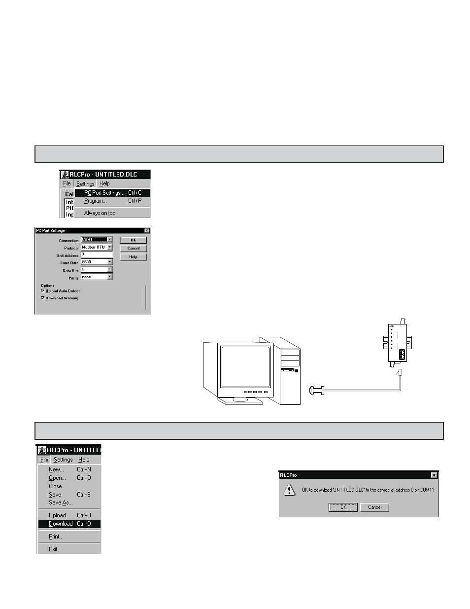
STEP 17 PC PORT CONFIGURATION
Go to the SETTINGS pull-down menu, and select PC PORT SETTINGS.
The Communications Settings window allows you to set up the software properly to perform a download.
Connection: Select the computer port (COMM 1-4) that the DLC is connected to.
Note: The following settings must match the DLC. If you do not know or cannot recall the DLC settings, they can
be temporarily set to factory defaults. Simply jumper the Default Serial Setting terminal 7 to Input Common
terminal 4 or put the Default Serial Settings DIP switch in the “UP” position. The serial settings will default
to RTU mode, 9600 baud, 8 data bits, no parity, with an address of 247.
Protocol: RTU or ASCII
Unit Address: 1-247
Baud Rate: 300, 600, 1200, 2400, 4800, 9600, 19200, 38400
Data Bits: 7 or 8
Parity: odd, even, or none
BOTH FLASHING
ALL FLASHING = CHECKSUM ERROR
INPUT ERROR
RS485
MODBUS
PROTOCOL
CH B ALM
=
PWR/COMM.
INPUT ERROR
BOTH FLASHING
CH A ALM
AUTOTUNE
CH B OP
CH A OP
=
CBPRO
DLC
MODEL DLC
RED LION CONTROLS
Note: The CBPRO007 download cable DOES NOT
typically require power. In most cases it will derive
its power from the PC. If communications can not be
established, follow the troubleshooting guide. If it is
determined that the converter requires power, attach
a 12 VDC power supply to the VDC and common
terminals of the cable.
Connect the DLC to the computer with the CBPRO007 interface cable (or any suitable RS232/RS485 converter).
Apply power to the supply terminals of the DLC.
STEP 18 DOWNLOADING
Go to the FILE pull-down menu, and select DOWNLOAD.
The following screen prompts you to
ensure that the proper file is downloaded
to the correct controller. Click “OK” to
continue.