Step 13 programming the alarms, Alarm action figures – Red Lion DLC User Manual
Page 12
12
STEP 13 PROGRAMMING THE ALARMS
Alarm 1 and 2: The controller is equipped with two alarms for each channel. The status of these alarms
can be read through AL1 registers 40015/40031 and AL2 registers 40016/40032.
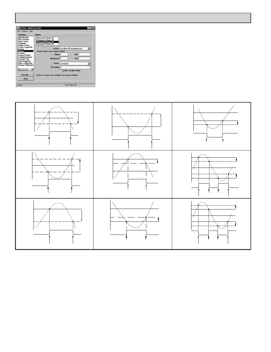
Action (40131/40231), (40136/40236): Select the action for the alarms. See Alarm Action Figures for a
visual explanation.
Manual: In Manual mode, the alarms are forced on and off by writing ‘0’ or ‘1’ to the appropriate
alarm output register. In this mode, the alarms will not respond to Alarm and Hysteresis Values.
Absolute HI (balanced or unbalanced hysteresis): The alarm energizes when the Process Value exceeds
the alarm.
Absolute LO (balanced or unbalanced hysteresis): The alarm energizes when the Process Value falls
below the alarm.
Deviation HI, Deviation LO, Band Acting: In these actions, Alarm 1 and 2 value tracks the Setpoint
value.
Cooling (OP2): For heat/cool applications, select Cool for Alarm 2. The controller then utilizes the
Alarm 2 output as the Cooling Output (OP2). If cooling is selected, the remaining Alarm 2
parameters are not available.
OFF
ON
AL + ½Hys
AL
AL - ½Hys
OFF
Absolute High Acting (Balanced Hys)
Hys
TRIGGER POINTS
ALARM
STATE
OFF
ON
AL + ½Hys
AL
AL - ½Hys
OFF
Absolute Low Acting (Balanced Hys)
TRIGGER POINTS
Hys
ALARM
STATE
ALARM
STATE
OFF
ON
Hys
SP + AL
SP
OFF
TRIGGER POINTS
Deviation High Acting (AL > 0)
ALARM
STATE
Hys
SP - AL
SP
SP + AL
Hys
TRIGGER POINTS
ON
OFF
OFF
ON
ON
Band Inside Acting
ALARM
STATE
OFF
ON
Hys
SP - AL
SP
OFF
TRIGGER POINTS
Deviation Low Acting (AL > 0)
ALARM
STATE
OFF
ON
Hys
AL
AL - Hys
OFF
TRIGGER POINTS
Absolute High Acting (Unbalanced Hys)
ALARM
STATE
OFF
ON
Hys
AL + Hys
AL
OFF
TRIGGER POINTS
ALARM
STATE
ON
OFF
Hys
SP + (-AL)
SP
ON
TRIGGER POINTS
Deviation High Acting (AL< 0)
ALARM
STATE
ON
Hys
SP - AL
SP
OFF
SP + AL
ON
Hys
OFF
OFF
TRIGGER POINTS
ALARM ACTION FIGURES
Note: Hys in the above figures refers to the Alarm Hysteresis.
Value (40003/40019), (40004/40020): The alarm values are entered as process units or degrees.
Hysteresis (40134/40234), (40139/40239): The Hysteresis Value is either added to or subtracted from the alarm value, depending on the alarm action selected.
See the Alarm Action Figures for a visual explanation of how alarm actions are affected by the hysteresis.
Trigger Points: Trigger points are the Process Values where the alarm state changes. Their values cannot be entered directly, but are shown as a reference in the
SFDLC software. The alarm value, hysteresis value, and setpoint alarm type determine the trigger points. With Deviation or Band actions, the alarm value and
setpoint value are combined to determine the trigger points. Trigger points must not be greater than +32000 or less than -32000. If these limits are exceeded,
the alarm may not function properly.
Reset (40132/40232), (40137/40237): The alarms can be programmed for Automatic or Latched. In Automatic mode, an energized alarm turns off automatically
once the Process Value leaves the alarm region. In Latched mode, an energized alarm requires a manual reset. This is done by writing ‘0’ to the appropriate
output status register. After writing ‘0’, the Automatic or Latched alarm will not turn on again until after the Process Value first returns to the alarm off region.
Only alarms configured for Manual action can be energized by writing a ‘1’ to its’ alarm output status register.
On Delay (40135/40235), (40140/40240): The time, in seconds, required for the Process Value to be in the alarm region before the alarm will activate. It is used
to allow temporary or short excursions into the alarm region without tripping the alarm.
Enable Standby Delay (40133/40233), (40138/40238): Standby prevents nuisance (typically low level) alarms after a power up or setpoint change. After
powering up the controller or changing the setpoint, the process must leave the alarm region. Once this has occurred, the standby is disabled and the alarm
responds normally until the next controller power up or setpoint change.