Step 12 programming the outputs – Red Lion DLC User Manual
Page 11
11
Pause: Pause signifies that a profile is active but the time base (Profile Phase Timer) is paused. The pause mode can only be invoked by writing a
3 in the Profile Operating Status register. Pausing a profile during a ramp phase pauses the ramp and the controller maintains control at the
ramping setpoint value (40045/40053) at the instant of the pause action. The use of pause, effectively lengthens the total run time of a profile.
The unit will remain in pause mode until it is placed back in the run mode by writing a 2 (Run/Start) into the Profile Operating Status Register.
Error Delay (Guaranteed Soak): The Error Delay Setting is used only as a status indication. It indicates that a profile is active but the phase timer
or profile advancement has stopped. This is caused by automatic action of the controller when the process deviates more than a specified amount
from the active profile segment. The Error Delay is similar to pause, except the error delay status can only be invoked automatically. See "Profile
Error Band Mode (40322/40422)." Do not write a "4 - Error Delay," to the Profile Operating Status Register. Doing so will instead put the
controller in pause mode (3).
Profile Phase (40066/40074): When the profile is active, this register indicates whether the controller is in a ramp (0) or hold (1) phase.
Profile Segment (40067/40075): Indicates the current active segment while the profile is running. A zero indicates that the profile is stopped or off.
Profile Phase Timer (40068/40076): This register shows the remaining segment phase time in 10ths of minutes. The remaining phase time can be
changed "on the fly" to accelerate or decelerate the phase time. The change in phase time will only affect the running profile and not the stored
parameters. If the phase time is changed during the ramp phase, a new ramp rate will be calculated which will achieve the desired phase time. The
Profile Phase Timer will stop while the unit is paused or during an error delay caused by Profile Error Band operation (guaranteed soak).
Profile Cycle Count Remaining (40069/40077): Indicates the number of profile cycles that are yet to be run. If the Profile Cycle Count register
(40326/40426) is set to 250, the Profile Cycle Count Remaining Register will run continuously, resetting to "250" when reaching "0". This register
value can be changed, however, it will only affect the current run cycle. When the profile is stopped and re-started, the Profile Cycle Count
Remaining Register will be reloaded based on the "Profile Cycle Count (40326/40426)" value.
Advance Profile Phase (40070/40078): Writing a "1" to this register while the profile is running will cause the controller to advance immediately to
the beginning of the next ramp or hold phase. Using the advance operation shortens the total run time of the profile. If the profile is "paused," the
profile will advance but the profile will remain paused. The Profile can also be advanced while in the error delay mode.
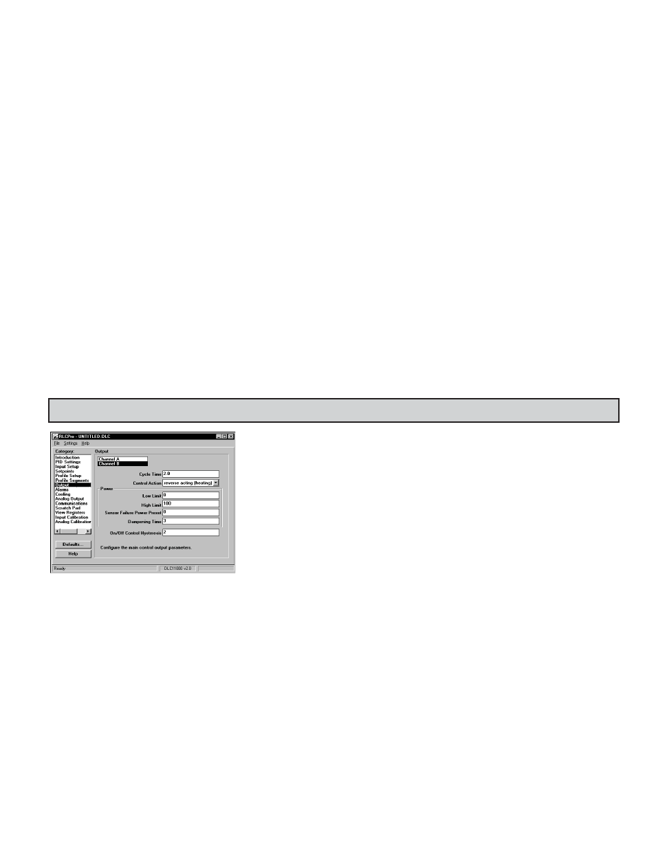
STEP 12 PROGRAMMING THE OUTPUTS
Cycle Time (40116/40216): The cycle time, entered in seconds, is the combined time of an on and off
cycle of a time proportioning control output OP1/OP2. With time proportional output, the percentage
of control power is converted into output on time of the cycle time value. (If the controller calculates
that 65% power is required and has a cycle time of 10 seconds, the output will be on for 6.5 seconds
and off for 3.5 seconds.) For best control, a cycle time equal to one-tenth of the process time constant,
or less, is recommended. When using the DC Analog output signal for control, a setting of zero will
keep output OP1 off. The status of OP1 can be read through registers 40014/40030.
Control Action (40117/40217): This determines the control action for the PID loop. Programmed for
direct action (cooling), the DLC output power will increase if the Process value is above the Setpoint
value. Programmed for reverse action (heating), the output power decreases when the Process Value is
above the Setpoint Value. For heat and cool applications, this is typically set to reverse. This allows
OP1 to be used for heating, and AL2/OP2 to be used for cooling.
Power Low Limit (40118/40218); High Limit (40119/40219): These parameters may be used to limit controller power due to process disturbances
or setpoint changes. Enter the safe output power limits for the process. If Alarm 2 is selected for cooling, the range is from -100 to +100%. At 0%,
both OP1 and OP2 are off; at 100%, OP1 is on; and at -100%, OP2 is on. When the controller is in Manual Control Mode, these limits do not apply.
Sensor Fail Power Preset (40120/40220): This parameter sets the power level for the control outputs in the event of a sensor failure or extreme
overdriven/underdriven input. If Alarm 2 is not selected for cooling, the range is from 0% (OP1 output full off) to 100% (OP1 output full on). If
AL2 is selected for cooling, the range is from -100 to +100%. At 0%, both OP1 and OP2 are off; at 100%, OP1 is on; and at -100%, OP2 is on. The
alarm outputs are upscale drive with an open sensor, and downscale drive with a shorted sensor (RTD only), independent of this setting. Manual
Control overrides the sensor fail preset.
Dampening Time (40121/40221): The dampening time, entered as a time constant in seconds, dampens (filters) the calculated output power.
Increasing the value increases the dampening effect. Generally, dampening times in the range of one-twentieth to one-fiftieth of the controller’s
integral time (or process time constant) is effective. Dampening times longer than these may cause controller instability due to the added lag effect.
On/Off Control Hysteresis (40122/40222): The controller can be placed in the On/Off Control Mode by setting the Proportional Band to 0.0%. The
On/Off Control Hysteresis (balanced around the setpoint) eliminates output chatter. In heat/cool applications, the control hysteresis value affects
both Output OP1 and Output OP2 control. It is suggested to set the hysteresis band to 2 (Factory Setting) prior to starting Auto-Tune. After Auto-
Tune, the hysteresis band has no effect on PID Control. On/Off Control Hysteresis is illustrated in the the On/Off Control Mode section.