Step 4 wiring the controller, Wiring connections, 21 tbb – Red Lion DLC User Manual
Page 6
6
9
5
8
6
7
10
4
3
TBA
12
+24VDC OUT
DC+ / (AC)
DC- / (AC)
OUTPUT COMMON
ต
OP1
AL1
AL2/OP2
+
-
Load
Load
Load
+
-
-
+
-
+
(200 mA max)
ต
Load Power from DLC
External Controller Power
CH A = Terminals 5, 6, & 7
CH B = Terminals 8, 9, & 10
Load
+
9
Load
+
-
+
TBA
+24VDC OUT
DC- / (AC)
DC+ / (AC)
OUTPUT COMMON
1
2
3
4
-
5
8
6
OP1
AL1
Load
+
-
-
7
10
AL2/OP2
-
+
ต
ต
Separate External Power
For Load and Controller
ต
ต
Load
+
9
Load
+
-
+
TBA
+24VDC OUT
DC- / (AC)
DC+ / (AC)
OUTPUT COMMON
1
2
3
4
-
5
8
6
OP1
AL1
Load
+
-
-
7
10
AL2/OP2
Combined External Power
For Load and Controller
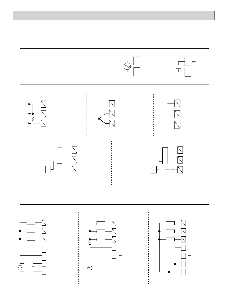
CONTROL AND ALARM OUTPUT CONNECTIONS
CH A = Terminals 5, 6, & 7
CH B = Terminals 8, 9, & 10
CH A = Terminals 5, 6, & 7
CH B = Terminals 8, 9, & 10
* For two wire RTDs, install a copper sense lead of the same gauge and length as the RTD leads. Attach one end of the wire at the probe and the other end to input
common terminal. Complete lead wire compensation is obtained. This is the preferred method. If a sense wire is not used, then use a jumper. A temperature offset
error will exist. The error may be compensated by programming a temperature offset.
** +24 VDC OUT (Terminal 3) shares common with Ch A Inputs & All Control/Alarm Outputs.
0-10V, 0-20mA
RTD EXC.
TC+ OR RTD
INPUT COMMON
5
2
3
6
1
4
TBB
Exc./
Jumper
Sense
Sense
RTD and Resistance
*
CH A = Terminals 4, 5 & 6
CH B = Terminals 1, 2 & 3
4
TBB
1
2
5
TC+ OR RTD
INPUT COMMON
3
6
RTD EXC.
0-10V, 0-20mA
TC+
TC-
Thermocouple and Millivolt
CH A = Terminals 4, 5 & 6
CH B = Terminals 1, 2 & 3
2
1
TBB
DC-
DC+
INPUT COMMON
TC+ OR RTD
45
3
0-10V, 0-20mA
6
RTD EXC.
Voltage or Current
CH A = Terminals 4, 5 & 6
CH B = Terminals 1, 2 & 3
2
TBB
TC+ OR RTD
INPUT COMMON
4
1
5
RTD EXC.
0-10V, 0-20mA
3
6
+24VDC OUT
(200 mA max)
LOAD
TBA
3
+
-
2 Wire Current Signal Requiring DLC Excitation **
CH A = Terminals 4, 5 & 6
CH B = Terminals 1, 2 & 3
(200 mA max)
+24VDC OUT
TC+ OR RTD
RTD EXC.
0-10V, 0-20mA
INPUT COMMON
LOAD
TBA
3
TBB
1
2
45
3
6
Vs
Out
Comm
3 Wire Current or Voltage Signal Requiring DLC Excitation **
CH A = Terminals 4, 5 & 6
CH B = Terminals 1, 2 & 3
INPUT CONNECTIONS
STEP 4 WIRING THE CONTROLLER
(AC)
(AC)
TBA
2
1
~
~
1
TBA
DC+
DC-
2
-
+
24 VAC POWER
18 to 36 VDC POWER
WIRING CONNECTIONS
All conductors should meet voltage and current ratings for each terminal. Also, cabling should conform to appropriate standards of good installation, local codes
and regulations. When wiring the controller, use the numbers on the label to identify the position number with the proper function. Strip the wire, leaving
approximately 1/4" (6 mm) of bare wire exposed. Insert the wire into the terminal, and tighten the screw until the wire is clamped tightly. (Pull wire to verify
tightness.) Each terminal can accept up to one #14 AWG (2.55 mm), two #18 AWG (1.02 mm), or four #20 AWG (0.61 mm) wires.
CONTROLLER POWER CONNECTIONS
For best results, the power should be relatively “clean” and within the
specified limits. Drawing power from heavily loaded circuits or from circuits
that also power loads that cycle on and off should be avoided. It is recommended
that power supplied to the controller be protected by a fuse or circuit breaker.