Specifications, Communications, Software – Red Lion DLC User Manual
Page 2: Analog output option
2
COMMUNICATIONS
The RS485 serial communications allows the DLC to be multi-dropped, with
Baud rates up to 38400. The CBPRO007 programming cable converts the
RS232 port of a PC to RS485 and is terminated with an RJ11 connector. The
bi-directional capability of the CBPRO007 allows it to be used as a permanent
interface cable as well as a programming cable.
SOFTWARE
The DLC is programmed with Windows
®
based SFDLC software. The
software allows configuration and storage of DLC program files, as well as
calibration. Additionally, all setup and control parameters can be interrogated
and modified through MODBUS™ register and coil commands.
ANALOG OUTPUT OPTION
The optional dual DC Analog Output (10 V or 20 mA) can be independently
configured and scaled for control or re-transmission purposes. These outputs can
be assigned to separate channels, or both outputs can be assigned to the same
channel. Programmable output update time reduces valve or actuator activity.
SPECIFICATIONS
1. POWER:
18 to 36 VDC, 13 W (4 W if +24 VDC Output excitation is unused)
24 VAC, ±10% 50/60 Hz, 15 VA (7 VA if +24 VDC Output excitation is unused)
Must use a Class 2 or SELV rated power supply.
2. +24 VDC OUTPUT POWER: 24 VDC, +15%, -5%, 200 mA max
3. MEMORY: Non-volatile memory retains all programmable parameters.
4. INPUT:
Sample Time: 100 msec (9.5 Hz)
Failed Sensor Response: Open or shorted (RTD only) sensor coils
indication, error code returned in Process Value
Common Mode Rejection: >110 dB, 50/60 Hz
Normal Mode Rejection: >40 dB, 50/60 Hz
Temperature Coefficient: 0.013%/°C
Overvoltage: 50 VDC max
Step Response Time: 300 msec typ., 400 msec max
5. THERMOCOUPLE INPUTS:
Types: T, E, J, K, R, S, B, N, C, linear mV
Input Impedance: 20 M
Lead Resistance Effect: 0.25 μV/
Cold Junction Compensation: Less than ±1°C typical (±1.5°C max) over
0 to 50°C ambient temperature range or less than ±1.5°C typical (2°C
max) over -20 to 65°C maximum ambient temperature range.
Resolution: 1° or 0.1° for all types except linear mV (0.1 or 0.01 mV)
TYPE
MEASUREMENT
RANGE
WIRE COLOR
ANSI
BS 1843
T
-200 to +400°C
-328 to +752°F
(+) Blue
(-) Red
(+) White
(-) Blue
E
-200 to +750°C
-328 to +1382°F
(+) Violet
(-) Red
(+) Brown
(-) Blue
J
-200 to +760°C
-328 to +1400°F
(+) White
(-) Red
(+) Yellow
(-) Blue
K
-200 to +1250°C
-328 to +2282°F
(+) Yellow
(-) Red
(+) Brown
(-) Blue
R
0 to +1768°C
+32 to +3214°F
No Standard
(+) White
(-) Blue
S
0 to +1768°C
+32 to +3214°F
No Standard
(+) White
(-) Blue
B
+149 to +1820°C
+300 to +3308°F
No Standard
No Standard
N
-200 to +1300°C
-328 to +2372°F
(+) Orange
(-) Red
(+) Orange
(-) Blue
C
W5/W6
0 to +2315°C
+32 to +4199°F
No Standard
No Standard
mV
-5 mV to 56 mV
N/A
N/A
6. RTD INPUTS:
Type: 2 or 3 wire
Excitation: 150 μA
Lead Resistance: 15
max
Resolution: 1 or 0.1° for all types
TYPE
INPUT TYPE
RANGE
385
100
platinum, Alpha = .00385
-200 to +600°C
-328 to +1100°F
392
100
platinum, Alpha = .003919
-200 to +600°C
-328 to +1100°F
672
120
nickel, Alpha = .00672
-80 to +215°C
-112 to +419°F
ohms
Linear Resistance
0 to 320
7. TEMPERATURE INDICATION ACCURACY: ± (0.3% of span, +1°C).
Includes NIST conformity, cold junction effect, A/D conversion errors,
temperature coefficient and linearization conformity at 23 °C after 20 minute
warm up.
8. PROCESS INPUT:
INPUT RANGE
ACCURACY *
(18 to 28°C)
(10 to 75% RH)
IMPEDANCE
MAX
CONTINUOUS
OVERLOAD
RESOLUTION
10 VDC
(-1 to 11)
0.10% of
reading
+0.02 V
1 M
50 V
1 mV
20 mA DC
(-2 to 22)
0.10% of
reading
+0.03 mA
10
100 mA
1 μA
* Accuracies are expressed as
±
percentages after 20 minute warm-up.
9. ISOLATION LEVEL: 500 VAC @ 50/60 Hz, for one minute (50 V
working) between the following groups:
Ch A Input
Ch B Input
Control and Alarm Outputs
RS485/Analog Output
1
Power Supply
Note:
1
RS485 and Analog Outputs are not internally isolated. Their commons
must not be connected together externally for proper unit function (i.e.,
earth ground).
10. SERIAL COMMUNICATIONS:
Type: RS485; RTU and ASCII MODBUS modes
Baud: 300, 600, 1200, 2400, 4800, 9600, 19200, and 38400
Format: 7/8 bits, odd, even, and no parity
Transmit Delay: Programmable: See Transmit Delay explanation.
Transmit Enable (TXEN): (primarily for 20 mA loop converter) open
collector V
OH
= 10 VDC max, V
OL
= 0.5 VDC @ 5 mA max current limit
11. A/D CONVERTER: 16 bit resolution
12. CONTROL AND ALARM OUTPUTS:
Type: Non-isolated switched DC, N Channel open drain MOSFET
Current Rating: 1 A max
V
DS ON
: 0.3 V @ 1 A
V
DS MAX
: 30 VDC
Offstate Leakage Current: 0.5 mA max
13. MAIN CONTROL:
Control: PID or On/Off
Output: Time proportioning or DC Analog
Cycle Time: Programmable
Auto-Tune: When selected, sets proportional band, integral time, derivative
time values, and output dampening time
Probe Break Action: Programmable
14. ALARM: 1 or 2 alarms
Modes:
Manual (through register/coil)
Absolute High Acting (Balanced or Unbalanced Hysteresis)
Absolute Low Acting (Balanced or Unbalanced Hysteresis)
Deviation High Acting
Deviation Low Acting
Inside Band Acting
Outside Band Acting
Reset Action: Programmable; automatic or latched
Standby Mode: Programmable; enable or disable
Hysteresis: Programmable
Sensor Fail Response: Upscale
15. COOLING: Software selectable (overrides Alarm 2).
Control: PID or On/Off
Output: Time proportioning or DC Analog
Cycle Time: Programmable
Proportional Gain Adjust: Programmable
Heat/Cool Deadband Overlap: Programmable
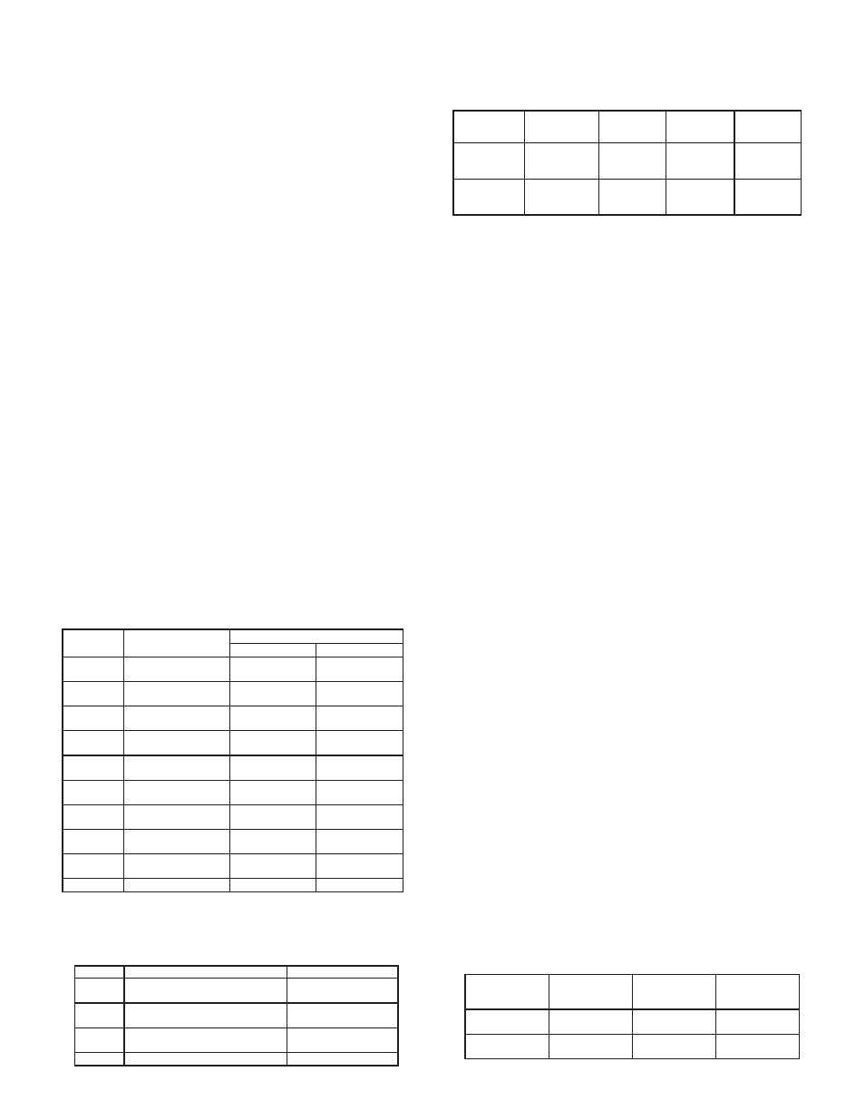
16. ANALOG DC OUTPUTS: (optional)
Control or retransmission, programmable update rate from 0.1 sec or
1 to 250 sec
Step Response Time: 100 msec
OUTPUT
RANGE**
ACCURACY *
(18 to 28°C)
(10 to 75% RH)
COMPLIANCE
RESOLUTION
(TYPICAL)
0 to 10 V
0.10% of FS
+ 1/2 LSD
10 K
min
1/18000
0 to 20 mA
0.10% of FS
+ 1/2 LSD
500
max
1/18000