Step 16 programming the dlc comms port, Step 15 programming the analog output (optional) – Red Lion DLC User Manual
Page 14
14
STEP 16 PROGRAMMING THE DLC COMMS PORT
Note: If the software selectable communication settings are changed and then a download is performed, the
controller will immediately respond to the new settings. Any further attempts to communicate to the controller
must target the new address, with the new settings.
SERIAL SETTINGS
MODBUS Protocol (40405): RTU or ASCII
Unit Address (40401): 1-247
Baud Rate (40402): 300 to 38400
Data Bits (40404): 7 or 8
Parity (40403): odd, even, or none
Transmit Delay (40406): Programmable from 2-250 milliseconds.
The Transmit Delay is the time the DLC waits to respond to a serial
command, UNLESS the values in the table are larger.
Note: Changing the above parameters by writing to their registers
directly will not update the DLC until Load Serial Settings register
40407 is a ‘1’. After a write, this register will return to ‘0’.
DIP Switch Serial Settings: The DIP switches can be used to select the
baud rate, parity, and unit address. When using the DIP switches to
configure the serial settings, the Modbus communications mode will be RTU only. There is also a "Default Serial
Settings" switch to quickly configure the DLC for use with the "RLCPRO" Programming Software.
Software Selectable Serial Settings: Setting all of the DIP switches to the "off" position and having the "Default
Serial Setting" terminal un-connected, enables Software Selectable Serial settings. When leaving the factory the
Software Selectable serial settings are set to the Serial Communication Defaults. Software Selectable Serial
Settings allows set-up of all serial settings including the choice of RTU or ACSII communications modes and the
number of data bits. If the Software Selectable Serial Settings are changed, the load serial register must be used
or power to the DLC must be removed and re-applied in order for the settings to take effect. The use of RLCPRO
Programming software or another software program supporting Modbus protocol is required to write to the DLC
serial settings registers (40401-40407).
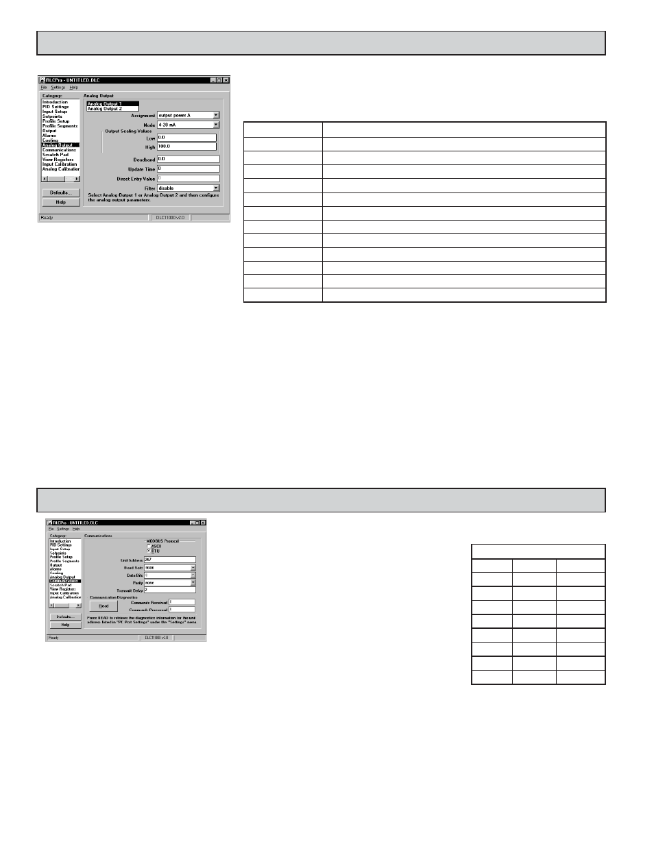
STEP 15 PROGRAMMING THE ANALOG OUTPUT (Optional)
Note: The register numbers correspond to (Analog Output 1/Output 2).
Assignment (40301/40309): This setting selects the value that the Analog Output will retransmit, or track.
The Analog output can be assigned for the following:
Mode (40302/40310): Select the type of output and range. The Analog output jumpers must be set to match the
output type and range selected. The Analog output can be calibrated to provide up to 5% of over range operation.
Output Scaling Values: The Scaling Low value (40303/40311) corresponds to 0 V, 0 mA or 4 mA, depending on
the range selected. The Scaling High value (40304/40312) corresponds to 10 V or 20 mA depending on the range
selected. An inverse acting output can be achieved by reversing the Scaling Low and Scaling High points.
Deadband (40305/40313): The output power change must be greater than the deadband value in order for the
Analog output to update. This only applies when the Analog Output is assigned to Output Power. This setting
can be used to reduce actuator activity.
Update Time (40306/40314): To reduce excess valve actuator or pen recorder activity, the update time of the
analog output can be set in seconds. A value of zero seconds results in an update time of 0.1 second.
Direct Entry Value (40307/40315): If the analog output is programmed for Direct Entry, it retransmits this value.
This value may be controlled by the host.
Filter (40308-40316): Entering a 1 will apply averaging when the Update Time >=1.
SELECTION
DESCRIPTION
Output Power A
Process Value A
Retransmits Process Value Channel A
Setpoint A
Retransmits Setpoint Value Channel A
Ramping Setpoint A
Retransmits Ramping Setpoint Channel A
Deviation A
Retransmits Deviation (difference of Setpoint Value - Process Value) Channel A
Direct Entry Value 1
Retransmits Direct Entry Value 1 (Manual Analog Control)
Output Power B
Transmits the Output Power demand of Channel B. Used if linear control is desired.
Process Value B
Retransmits Process Value Channel B
Setpoint B
Retransmits Setpoint Value Channel B
Ramping Setpoint B
Retransmits Ramping Setpoint Channel B
Deviation B
Retransmits Deviation (difference of Setpoint Value - Process Value) Channel B
Direct Entry Value 2
Retransmits Direct Entry Value 2 (Manual Analog Control)
Transmits the Output Power demand of Channel A. Used if linear control is desired.
MINIMUM TRANSMIT DELAY
BAUD
RTU
ASCII
38400
2 msec
2 msec
19200
3 msec
2 msec
9600
5 msec
2.3 msec
4800
9 msec
4.6 msec
2400
17 msec
9.2 msec
1200
33 msec
18.4 msec
600
65 msec
36.7 msec
300
129 msec
73.4 msec