Block diagram, Accuracies are expressed as – Red Lion DLC User Manual
Page 3
3
OUTPUT
RANGE**
ACCURACY *
(18 to 28°C)
(10 to 75% RH)
COMPLIANCE
RESOLUTION
(TYPICAL)
4 to 20 mA
0.10% of FS
+ 1/2 LSD
500
max
1/14400
* Accuracies are expressed as
±
percentages after 20 minute warm-up.
** Outputs are independently jumper selectable for either 10 V or 20 mA.
The output range may be field calibrated to yield approximate 10%
overrange and a small underrange (negative) signal.
17. ENVIRONMENTAL CONDITIONS:
Operating Temperature Range: -20 to +65°C
Storage Temperature Range: -40 to +85°C
Operating and Storage Humidity: 85% max relative humidity,
noncondensing, from -20 to +65°C
Vibration according to IEC 68-2-6: Operational 5 to 150 Hz, in X, Y, Z
direction, duration: 1.5 hours, 2 g.
Shock according to IEC 68-2-27: Operational 30 g, 11 msec in 3 directions.
Altitude: Up to 2000 meters
18. CERTIFICATIONS AND COMPLIANCE:
SAFETY
UL Recognized Component, File # E156876, UL873, CSA 22.2 No. 24
Recognized to U.S. and Canadian requirements under the Component
Recognition Program of Underwriters Laboratories, Inc.
IEC 61010-1, EN 61010-1: Safety requirements for electrical equipment
for measurement, control, and laboratory use, Part I
ELECTROMAGNETIC COMPATIBILITY
Emissions and Immunity to EN 61326:2006: Electrical Equipment for
Measurement, Control and Laboratory use.
Immunity to Industrial Locations:
Electrostatic discharge
EN 61000-4-2
Criterion A
2
4 kV contact discharge
8 kV air discharge
Electromagnetic RF fields EN 61000-4-3
Criterion A
3a
10 V/m (80 MHz to 1 GHz)
3 V/m (1.4 GHz to 2 GHz)
1 V/m (2 GHz to 2.7 GHz)
Fast transients (burst)
EN 61000-4-4
Criterion B
power 2 kV
I/O signal 1 kV
Surge
EN 61000-4-5
Criterion A
power 1 kV L to L, 2 kV L to G
RF conducted interference EN 61000-4-6
Criterion A
3 Vrms
Power freq magnetic fields EN 61000-4-8
30 A/m
AC power
EN 61000-4-11
Voltage dip
Criterion
0% during 1 cycle A
40% during 10/12 cycle C
70% during 25/30 cycle C
Short interruptions
Criterion
0% during 250/300 cycles C
Emissions:
Emissions
EN 55011
Class A
1
Criterion A: Normal operation within specified limits.
2
This controller was designed for installation in an enclosure. To avoid
electrostatic discharge to the unit in environments with static levels above 6
kV, precautions should be taken when the device is mounted outside an
enclosure. When working in an enclosure (ex. making adjustments, setting
switches etc.), typical anti-static precautions should be observed before
touching the unit.
3
Criterion B: Temporary loss of performance from which the unit self-recovers.
a.
Note: The module's analog input and/or output signals may deviate during
disturbance, but self-recover when disturbance is removed. For operation
without loss of performance: Unit is mounted in a metal enclosure I/O and
power cables are routed in metal conduit connected to earth ground.
4
Criterion C: Temporary loss of function where system reset occurs. 19.
CONSTRUCTION: Case body is black high impact plastic. Installation
Category I, Pollution Degree 2.
20. CONNECTIONS: Wire clamp screw terminals. Removable terminal blocks.
21. MOUNTING: Snaps on to standard DIN style top hat (T) profile mounting
rails according to EN50022 -35 x 7.5 and -35 x 15.
22. WEIGHT: 10.5 oz. (298 g.)
AL1
OP1
9
8
AL2/OP2
10
AL1
AL2/OP2
6
7
3
4
COMM.
5
POWER
INPUT
1
2
PROCESS
CIRCUITRY
TC+ / RTD
COMMON
2
INPUT B
1
0-10V, 0-20mA
4
5
3
7
6
10
ANALOG OUT 1 -
9
ANALOG OUT 1 +
8
11
24 VDC
OP1
SUPPLY
POWER
-0.6V
+13.3V
+18V
+5VS
-3.6VS
+5VC
+5VC DIG
-3.6VC
+5VS DIG
+5V DIG
24VDC
24V
24V
E MEMORY
2
RS485
RTD EXC
INPUT A
INPUT A
INPUT B
RTD EXC
0-10V, 0-20mA
TC+ / RTD
COMMON
INPUT B
CONV.
A/D
4.02K
5VC
10 Ω
4.99K
976K
5VC
20M
0-10V, 0-20mA
ANALOG OUT 2 -
0-10V, 0-20mA
ANALOG OUT 2 +
ISOLATED
V+
I+
I-
V-
A/D
CONV.
4.02K
5VS
10 Ω
4.99K
976K
5VS
20M
+18V
25.5 Ω
DIG
+18V
INPUT A
25.5 Ω
(PWM)
CONV.
D/A
D/A
CONV.
(PWM)
I-
V-
I+
V+
ISOLATED
5VC
OUTPUT
ANNUNCIATORS
C
C
C
S
S
S
O
O
O
O
O
O
O
O
I
I
I
I
I
I
I
B-
A+
GND
TXEN
U
MAIN DIG
U
D
5V DIG
24V
24V
24V
24V
(DO NOT CONNECT AND )
O
U
DIP SWITCHES
TBB
TBA
DEFAULT
SERIAL
SETTINGS
+5V MAIN DIG
+24V OUT
+2.5V
o
5V
o
5V MAIN
5V MAIN
DIG
ISOLATED
5VS
D
D
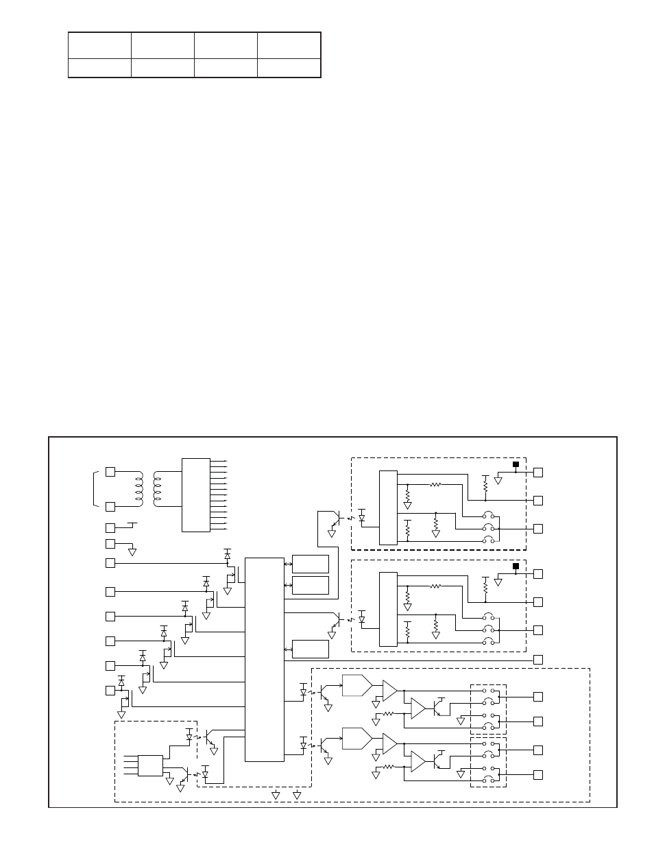
BLOCK DIAGRAM