Step 2 installing the controller, Step 3 identifying the leds - led functionality, Installation – Red Lion DLC User Manual
Page 5
5
SWA
DEFAULT SERIAL
SETTINGS
1
Use DIP Switch or
Software Serial Settings
DN
Use Default Serial
Settings
UP
PARITY
SWITCH POSITION
2
3
None
DN
DN
None
UP
Even
UP
DN
Odd
UP
UP
DN
BAUD RATE
SWITCH POSITION
4
5
6
300
DN
DN
DN
600
DN
DN
UP
1200
DN
UP
DN
2400
DN
UP
UP
4800
UP
DN
DN
9600
UP
DN
UP
19200
UP
UP
DN
38400
UP
UP
UP
UNIT ADDRESS
1
(128)
2
(64)
3
(32)
4
(16)
5
(8)
6
(4)
7
(2)
DN
DN
DN
DN
DN
DN
DN
DN
1
DN
DN
DN
DN
DN
DN
DN
UP
2
DN
DN
DN
DN
DN
DN
UP
DN
3
DN
DN
DN
DN
DN
DN
UP
UP
4
DN
DN
DN
DN
DN
UP
DN
DN
5
DN
DN
DN
DN
DN
UP
DN
UP
6
DN
DN
DN
DN
DN
UP
UP
DN
7
DN
DN
DN
DN
DN
UP
UP
UP
8
DN
DN
DN
DN
UP
DN
DN
DN
…
247*
UP
UP
UP
UP
DN
UP
UP
UP
SWITCH POSITION / (BIT WEIGHT)
SWB
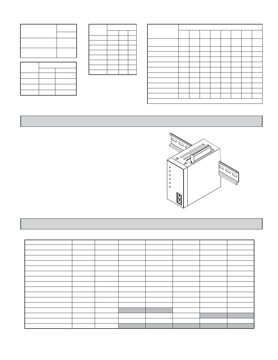
STEP 2 INSTALLING THE CONTROLLER
INSTALLATION
The controller is designed for attachment to standard DIN style top hat (T)
profile mounting rails according to EN50022 -35 x 7.5 and -35 x 15. The
controller should be installed in a location that does not exceed the maximum
operating temperature and provides good air circulation. Placing the controller
near devices that generate excessive heat should be avoided.
T Rail Installation
To install the DLC on a “T” style rail, angle the controller so that the top
groove of the mounting recess is located over the lip of the top rail. Push the
controller toward the rail until it snaps into place. To remove a controller from
the rail, insert a screwdriver into the slot on the bottom of the controller, and
pry upwards until it releases from the rail.
8
(1)
Software Selectable
Serial Settings
*- Unit will use address 247 for binary switch settings above 247
SWITCH
POSITION
STEP 3 IDENTIFYING THE LEDs - LED FUNCTIONALITY
CONDITION
CH A OP
CH A ALM
CH B OP
CH B ALM
PWR/COMM
PRIORITY
AUTOTUNE
Power Applied
-------
-------
-------
-------
On
1
-------
Communicating
-------
-------
-------
-------
Flashing
1
-------
OP1 On (Channel A) **
On
-------
-------
-------
-------
4
-------
OP1 On (Channel B) **
-------
-------
On
-------
-------
4
-------
AL1 On (Channel A) *
-------
On
-------
-------
-------
4
-------
AL1 On (Channel B) *
-------
-------
-------
On
-------
4
-------
AL2 On (Channel A) *
Fast Flashing
-------
-------
-------
4
-------
OP2 On [Cool](Channel A)
Fast Flashing
-------
-------
-------
-------
5
-------
OP2 On [Cool](Channel B)
-------
-------
Fast Flashing
-------
-------
5
-------
Auto-Tune On (Channel A)
-------
-------
-------
-------
-------
3
On
Auto-Tune On (Channel B)
-------
-------
-------
-------
-------
3
Fast Flashing
Input Error (Channel A)
Slow Flashing
Slow Flashing
-------
-------
-------
3
-------
Calibration Mode
Input Error (Channel B)
On
-------
On
-------
On
Slow Flashing
On
Slow Flashing
-------
2
-------
3
On
-------
Checksum Error
Slow Flashing
Slow Flashing
Slow Flashing
Slow Flashing
-------
1
Slow Flashing
AL2 On (Channel B) *
-------
-------
-------
Fast Flashing
-------
4
-------
* If AL1 & AL2 outputs are on at the same time, the ALM annunciator will alternate between On and Fast Flashing every ½ second.
** If OP1 and AL2/OP2 (configured for cool) outputs are on at the same time, the annunciator will only show the OP1 state. The OP2 state is only shown when OP1 is off.
On power-up, all LEDs are turned on briefly in an alternating pattern to allow visual check of LED functionality.
Serial Communication Defaults:
1
none
1
Start Bit
Parity:
Stop Bit:
9600
Baud Rate:
247
Address:
RTU
Protocol: