Rs-422/485 interface, F rs-422/485 interface o – Vaisala DMT346 User Manual
Page 53
Chapter 3 ________________________________________________________________ Installation
VAISALA ________________________________________________________________________ 53
0605-032
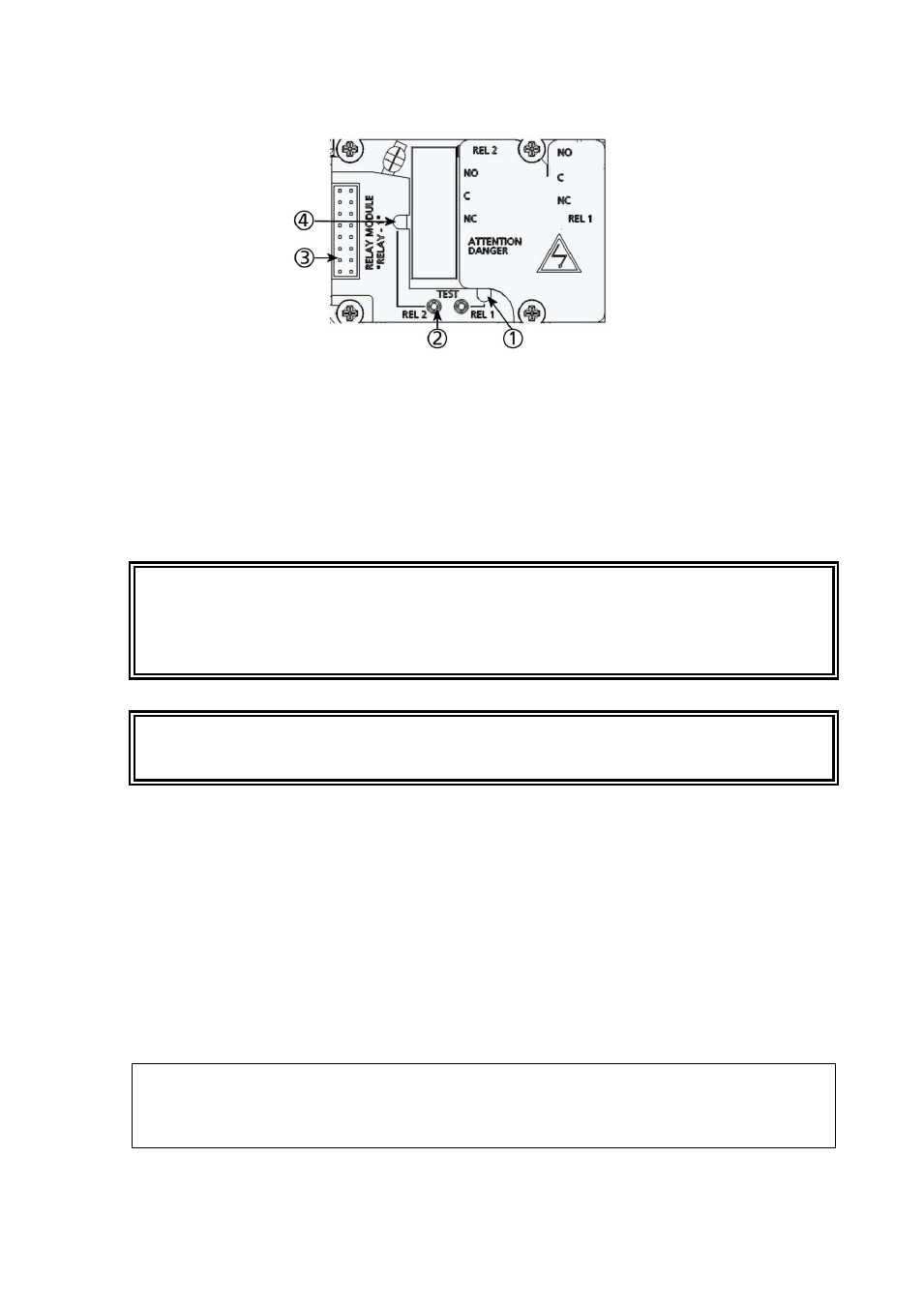
Figure 32
Relay Module
The following numbers refer to Figure 32 above:
1
=
Indication LED for the relay 1 or 3
2
=
Relay test buttons
3
=
Flat cable pins
4
=
Indication LED for relay 2 or 4
WARNING
The relay module may contain dangerous voltages even if the transmitter
power has been disconnected. Before working on the relay module you
must switch off both the transmitter and the voltage connected to the
relay terminals.
WARNING
Do not connect the mains power to relay unit without grounding the
transmitter.
RS-422/485 Interface
The RS-422/485 interface enables communication between an RS-485
network and the DMT345/346 transmitter. The RS-485 interface is
isolated and offers a maximum communications rate of 115 200 bits/s.
(For maximum bus length of 1 km, use bit rate 19200 b/s or less.)
When selecting an RS-232 to RS-485 converter for the network, avoid
self-powered converters, as they do not necessarily support the needed
power consumption.
NOTE
RS-232 User Port on DMT345/346 main board cannot be used and
connected when RS-485 module is connected. Service port operates
normally.