Installation and wiring – Vaisala DMT346 User Manual
Page 51
Chapter 3 ________________________________________________________________ Installation
VAISALA ________________________________________________________________________ 51
Installation and Wiring
1.
Disconnect the power. In case the analog output module is installed
in the factory, continue with the step 4.
2.
Open the transmitter cover and and fasten the analog output module
to the position for MODULE 2 with four screws. Refer to Figure 2
on page 23.
3.
Connect the flat cable between the analog output module and the
motherboard's connector for MODULE 2.
4.
Take out the protective plug from the cable gland and thread the
wires.
5.
Connect the wires to the screw terminals marked with Ch+ and
Ch- .
6.
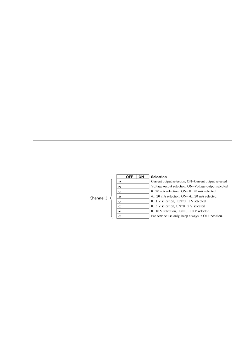
Select the current/voltage output by setting ON either of the
switches 1 or 2.
7.
Select the range by setting ON one of the switches 3 ... 7.
NOTE
Only one of the switches 1 … 2 can be ON at a time.
Only one of the switches 3 ... 7 can be ON at a time.
0508-029
Figure 31
Third Analog Output Selection
8.
Connect the power.
9.
Select the quantity and scale the channel via the serial line or
display/keypad, see section Analog Output Quantities on page 119.
For testing the analog output, see Section Analog Output Tests on
page 121. For fault indication setting, see section Analog Output
Fault Indication Setting on page 122.