Structure of the transmitter – Vaisala DMT346 User Manual
Page 22
User's Guide _______________________________________________________________________
22 ___________________________________________________________________ M210762EN-G
Structure of the Transmitter
1104-001
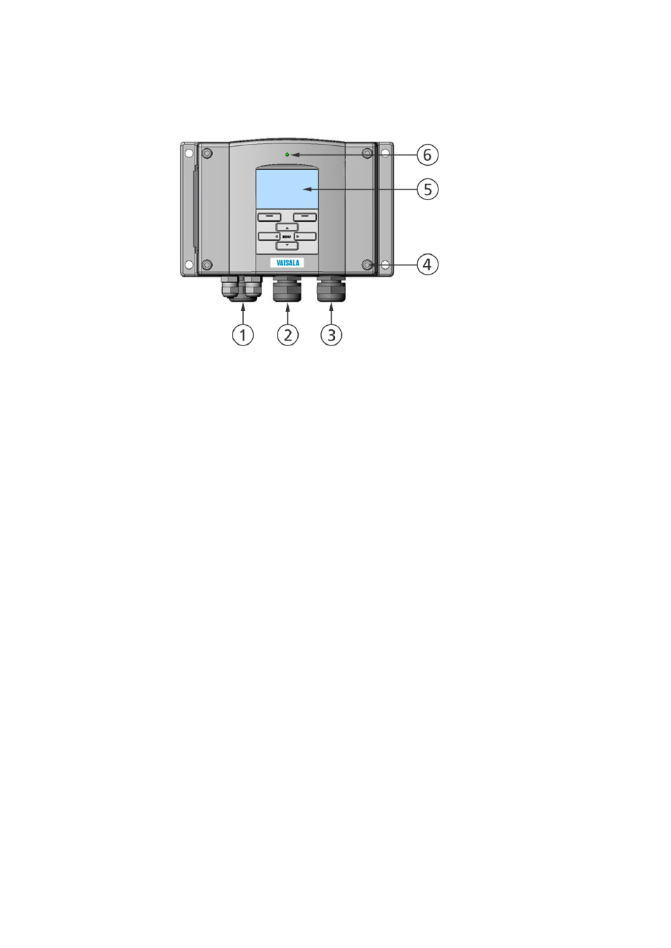
Figure 1
Transmitter Body
The following numbers refer to Figure 1 above:
1
=
Signal + powering cable gland
2
=
Cable gland for optional module, or WLAN antenna connector
3
=
Cable gland for optional module or AC mains cable
4
=
Cover screw (4 pcs)
5
=
Display with keypad (optional)
6
=
Cover LED
This manual is related to the following products: