Figure 12, Isolated current-loop wiring, Table 3 – Vaisala HMT120 User Manual
Page 24: Wiring table, Figure 12 a
User's Guide _______________________________________________________________________
22 ___________________________________________________________________ M211244EN-B
NOTE
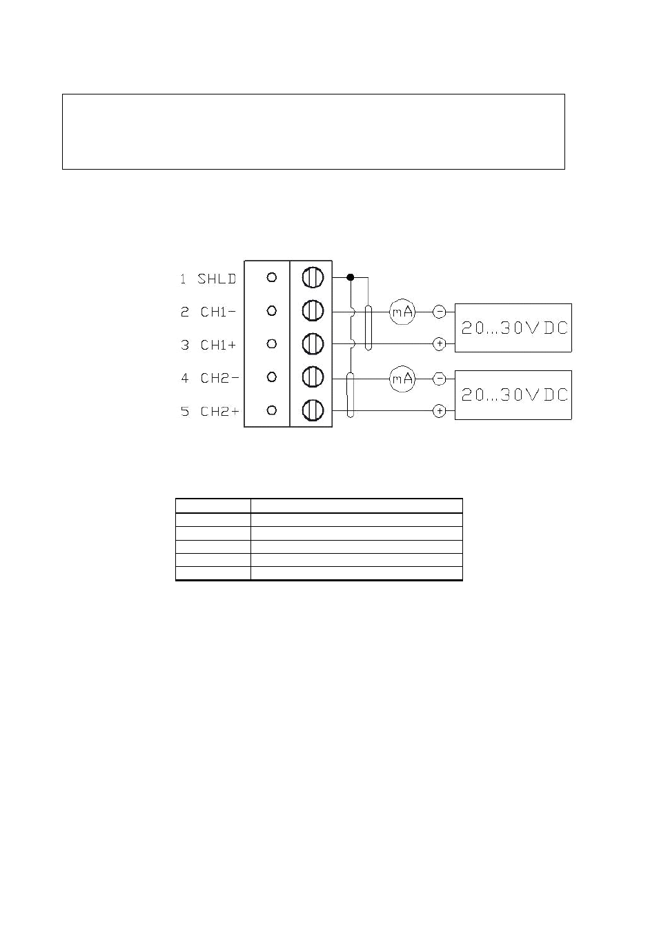
If an isolated output is required with current outputs, both channels
require their own power supply. CH1 is always required to be powered
because CH1 is the main output, and the transmitter will not operate if
only CH2 is connected.
4.
Close the cover by keeping it slightly tilted and first attaching it to
the fixing snaps at the top of the enclosure base and then pushing
the lower part of the cover firmly forward until it locks. The
transmitter is ready for use.
1011-152
Figure 12
Isolated Current-Loop Wiring
Table 3
Wiring Table
Terminal
Current Output (2-Wire, CH2 Isolated)
1
Cable shield (optional)
2
CH1- (signal and power supply -)
3
CH1+ (signal and power supply +)
4
CH2- (signal and power supply -)
5
CH2+ (signal and power supply +)
The numbers 1 ... 5 in the first column of the wiring table refer to Figure