Transmitter components, Figure 1, Hmt120 components – Vaisala HMT120 User Manual
Page 14
User's Guide _______________________________________________________________________
12 ___________________________________________________________________ M211244EN-B
Transmitter Components
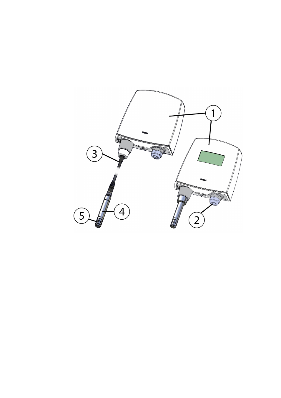
Figure 1 below illustrates the main features of HMT120. On the left is a
remote probe model without display, and on the right is a fixed probe
model with the optional display. The numbers and arrows indicate the
main components of the transmitters.
1007-001
Figure 1
HMT120 Components
The following numbers refer to Figure 1 above:
1 = Transmitter enclosure
2 = Cable bushing: cable gland, cable grommet, or conduit fitting.
3 = Probe cable
4 = HMP110 probe
5 = Plastic grid filter
See section Options and Accessories on page 73 for accessory parts and
their numbers.