Spw-10x spacewire router – Atmel SpaceWire Router SpW-10X User Manual
Page 45
Ref.: UoD_SpW-10X_
UserManual
Issue: 3.4
SpW-10X
SpaceWire Router
User Manual
Date: 11
th
July 2008
Preliminary
45
Note: The recommended method for setting the POR signals is to use external pull up/down resistors
(e.g. 4k7
Ω) in which case the timing of the POR signals is not critical.
See section 6.3 and 6.4 for further information on the operation of the status/ power on configuration
interface and section 10.5 for timing details.
5.7 POWER, GROUND, PLL AND LVDS SIGNALS
5.7.1 General
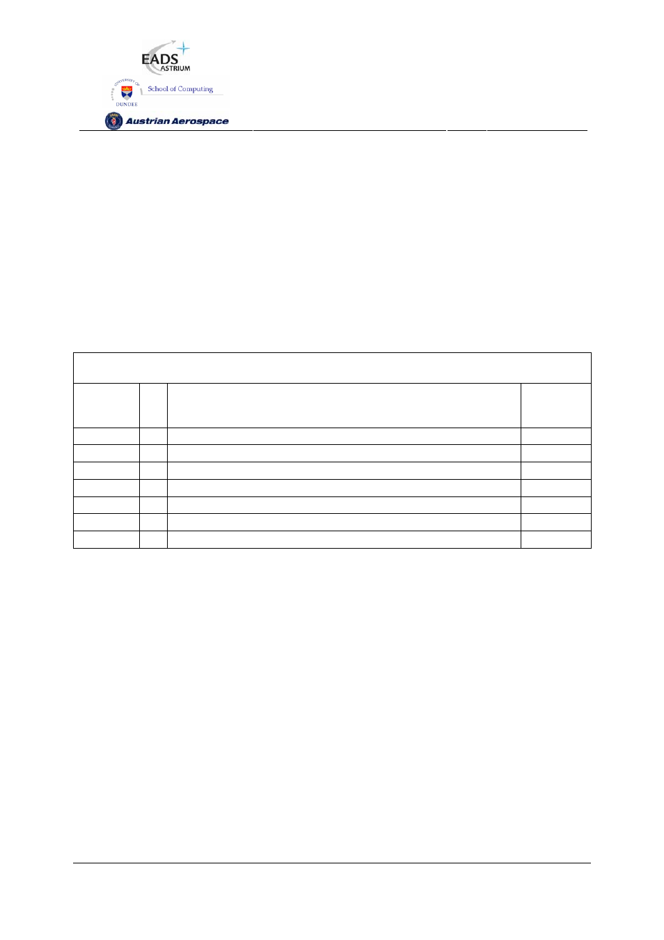
The Power, Ground and special signal connections are listed in Table 5-7.
Table 5-7 Power, Ground and Special Signals
Signal Dir
Description
Signal
Type
Power
-
3.3 V power for the device
3V3
Ground
-
Ground connection for the device
GND
VCOBias
PLL VCO Bias
analogue
VSSPLL
PLL
Supply
3V3
VDDPLL
PLL
Supply
GND
LoopFilter
PLL Loop Filter
analogue
LVDSref
LVDS Buffer reference
analogue
5.7.2 Decoupling
The power pins should be decoupled to the ground plane. One 100 nF decoupling capacitor should be
used for each power pin.
5.7.3 LVDS Reference
An external resistor is required to provide a reference for the LVDS buffers. A resistor with a value
between 16.3 k
Ω and 16.7 kΩ must be connected between LVDSref and ground.
5.7.4 PLL External Components
An internal PLL is used to provide the base transmit clock signal for the SpaceWire interfaces from the
CLK input. External components are required to implement the PLL loop filter and to provide a bias for
the PLL VCO. These components are illustrated in Figure 5-3. Note that R
VCO
, C and C0 are all
connected to a quiet common ground track.