Ag leader technology – Ag Leader GPS 3100 Operators Manual User Manual
Page 8
Antenna Installation
Add-On GPS 3000/3050/3100
Ag Leader Technology
June 2001
Rev. 1 3000124
6
Before mounting the Add-On GPS 3000/3050/3100 on your vehicle, the
user should test the system in the planned installation location. Turn on
all accessories or features of the vehicle that use electrical power,
examples being lights, air-conditioners, etc. In order to determine your
signal-to-noise-ratio (SNR) while installing your antenna, you must be on
the GPS Diagnostic screen of the PF3000. To view this screen:
Step
Action
1
Plug antenna jack into GPS unit.
2
Press the Menu key until DIAG is displayed and press DIAG
Key.
3
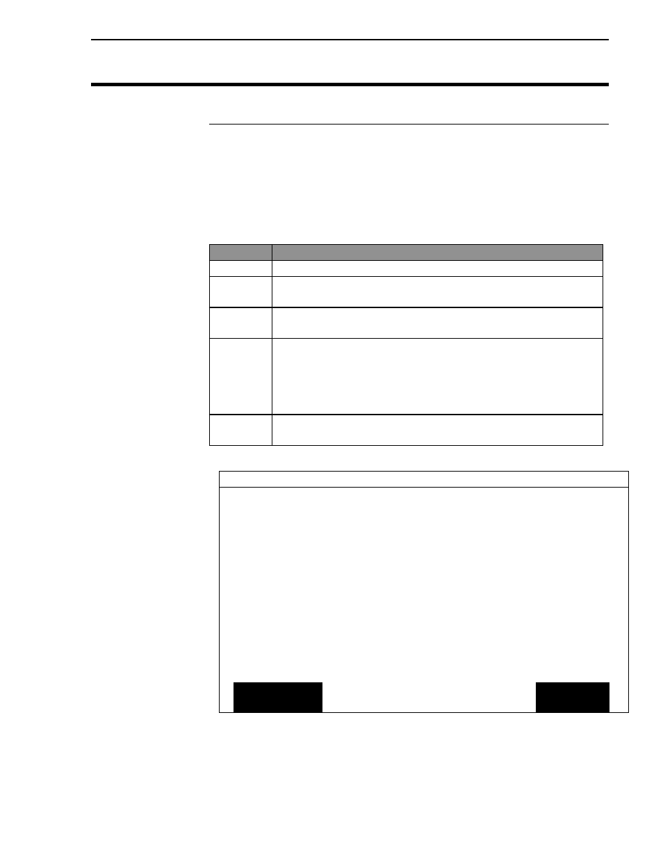
Press GPS key. NOTE: An example of the GPS Diagnostic
screen (Figure 1) is shown below.
Antenna
Installation
4
If the SNR drops below 6 or is lost completely, move the
antenna to a location where the signal is not as affected by
the interference. Moving the antenna horizontally or
vertically between 1 to 3 ft will usually eliminate the
problem.
5
Once you have completed positioning your antenna push
EXIT key.
GPS DIAGNOSTICS
UTC TIME
00:00:00
Latitude
0000.0000 S
Longitude
0000.0000 E
Elevation
0 ft
GPS speed
0.0 MPH
Number of satellites
0
Differential Status
OFF
Beacon/Sat. Frequency
0.000
Differential SNR
0.0
HDOP/PDOP
0.00/0.00
Antenna/Rcvr Voltage
5.00/13.73
ADD-ON
GPS
FORMAT
CARD
COPY TO
CARD
EXIT
Figure 1. GPS Diagnostic screen