Maintenance – Prochem Legend SE AD User Manual
Page 44
MAINTENANCE
LEGEND SE 980059 07/23/02
4-12
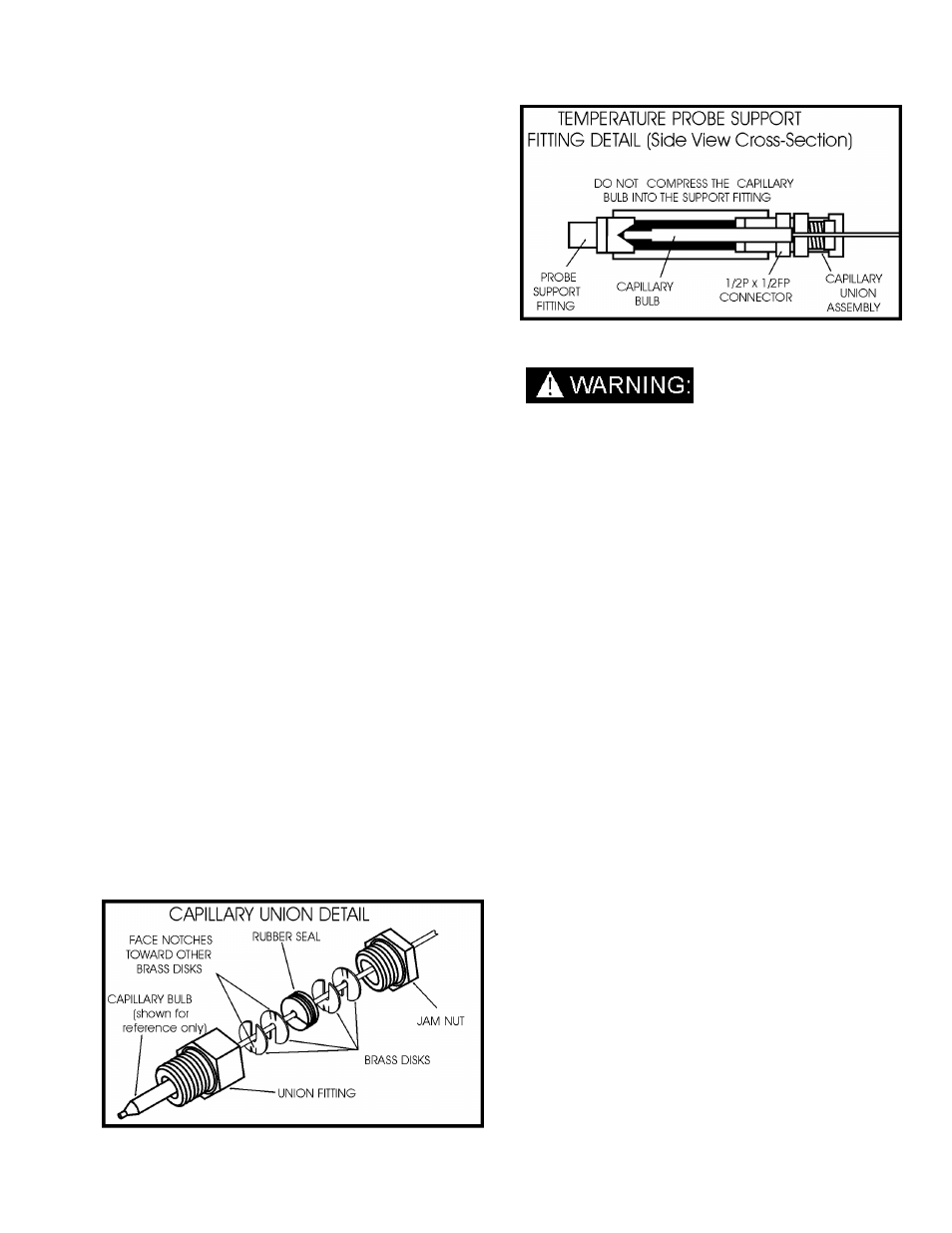
TEMPERATURE CAPILLARY & PACKING
ASSEMBLY
INSTALLATION INSTRUCTIONS
1. Using thread sealant, thread the tapered end of
the union fitting into the thermostat manifold and
tighten.
2. Slide the jam nut over the capillary bulb with the
threaded end toward the end of the capillary bulb.
3. Insert the capillary bulb through the union fitting
and into the thermostat manifold.
4. Place the rubber seal onto the capillary tube with
the split facing 90
°
from the top (see the capillary
union detail).
5. Fit the four brass disks onto the capillary tube,
with two of the brass disks on each side of the
rubber seal. Face the notch on one brass disk
toward the nearby brass disk to lock the brass
disks together. Then face the notches on the
brass disks 90
°
from the split in the rubber seal.
NOTE: Lubricating the facing sides of the brass
disks will hold them together on the capillary
tube during installation
.
6. Insert the rubber seal and brass disks into the
union fitting, hand tight.
7. Position the capillary bulb in the temperature
manifold as shown in the illustration. When
positioning the capillary bulb, do not allow the
bulb to compress against the support fitting.
8. Tighten the jam nut lightly, about 1-1/2 turns.
9. Examine the capillary union assembly for leaks
and tighten the union fitting just enough to stop
leaks. DO NOT over-tighten.
TROUBLESHOOTING
DO NOT service this unit while it is running. The
high-speed mechanical parts as well as high
temperature components may result in severe
injury, severed limbs, or fatality.
This chapter of the operator’s manual explains how to
look for and repair malfunctions which may occur.
Intelligent, accurate troubleshooting is based on a
complete and thorough understanding of the
WATER, VACUUM, CHEMICAL, HEAT TRANSFER,
SAFETY and WIRING systems on this unit.
If there is a malfunction occurring in a system which
you do not fully understand, turn back to the
"Operation" section of this manual and review
"Systems".
In addition, prior to proceeding, you can save
time by checking that:
1. The water supply is ON.
2. The engine speed at full throttle is 2600 RPM,
with the diverter valve in the HEAT EXCHANGER
position.
3. Check that water pump volume is correct. Check
the pump volume with the cleaning tool closed.
Measure the water flow returning to the water box
from the pressure regulator. The flow rate should
be 3.0 GPM. An additional .2 GPM of water
should be flowing through the bypass manifold
orifice, which is adjacent to the water box. If you
block the heat bypass flow, the flow rate will be
3.2 - 3.3 GPM.