NORD Drivesystems BU0090 User Manual
Page 64
NORDAC AS-Interface Manual
64
BU
0090
GB
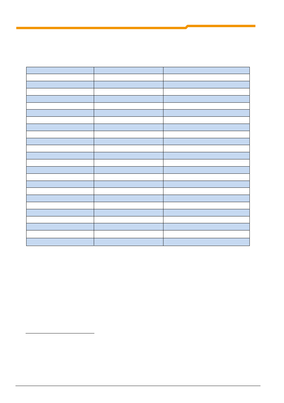
Parameterisation of functions:
Only the parameters relevant for the function of the I/Os are listed here. For further information, please refer to
the manuals BU0500 and BU0510.
Parameter / Array
Input and Output
Setting / Function
P420 digital input 1
DIN1 / digital input 1
01 = Enable right
P421 digital input 2
DIN2 / digital input 2
02 = Enable left
P422 digital input 3
DIN3 / digital input 3
08 = parameter set switch-over Bit 0
P423 digital input 4
DIN4 / digital input 4
17 = parameter set switch-over Bit 1
P424 digital input 5
DIN5 / digital input 5
13 = PTC input
P425 digital input 6
DIN6 / digital input 6
22 = Error acknowledgement
P470 digital input 7
DIN7 / digital input 7
23 = Reference point
P480 [05] Bus IO In Bit 4
Sensor input Dig In 1
55 = Bit 0 position (increment) array
P480 [06] Bus IO In Bit 5
Sensor input Dig In 2
56 = Bit 1 position (increment) array
P480 [07] Bus IO In Bit 6
Sensor input Dig In 3
57 = Bit 2 position (increment) array
P480 [08] Bus IO In Bit 7
Sensor input Dig In 4
58 = Bit 3 position (increment) array
P434 function output 1
Relay contact K1
1 = External brake
P441 function output 2
Relay contact K2
7 = Error
P450 function output 3
DOUT 1
3 = Current limit
P455 function output 4
DOUT 2
4 = Torque current limit
P481 [05] Bus IO Out Bit 5
Actuator output Dig Out 1
20 = Reference point
P481 [06] Bus IO Out Bit 6
Actuator output Dig Out 2
21 = Position reached
P509 interface
0 = Control terminals or keyboard
P543 Bus actual value 1
8
12 = Bus IO Out Bits 0…7
P546 Bus setpoint 1
9
17 = Bus IO Bits 0…7
The signal statuses of the I/O are only virtually displayed via the digital I/O LEDs with the SK TU1-AS1 and
SK TU3-AS1 AS interface modules. No I/O LEDs are available for the SK TU2-ASx modules.
In order to check the signal statuses of the IOs, the status can be checked via the information parameters
P7xx. The relevant array must be selected in the corresponding information parameter. The sensor inputs or
Bus IO In Bits are displayed in parameter P740 / process data Bus In.
The sensor inputs or Bus IO Out Bits are displayed in parameter P741 / process data Bus Out.
8
One of the three actual Bus values in parameters P543 to P545 must be parameterised on Bus IO Out Bits 0…7.
9
One of the three Bus setpoint values in parameters P546 to P548 must be parameterised on Bus IO Out Bits 0…7.