1 frequency inverter bus parameters – NORD Drivesystems BU0090 User Manual
Page 31
4 Frequency inverters - settings and control elements
BU 0090 GB
31
4 Frequency inverters - settings and control elements
Parameters and settings specific to the AS interface can be made via a ParameterBox or also via the
NORD CON software. For more detailed information, please refer to the corresponding operating instructions.
To ensure bus monitoring of the AS interface, the telegram downtime P513 should be parameterised by the
user. This prevents an uncontrolled start-up (with enabling via the bus) of the drive unit after restoration of the
bus connection.
4.1 Frequency inverter BUS parameters
In order to operate the frequency inverter with the AS interface, in addition to the bus connection to the master,
several parameter settings must be made on the frequency inverter.
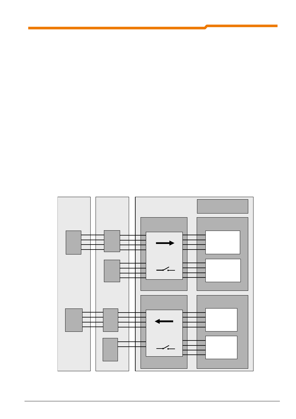
Control of the frequency inverter via the AS interface can be activated by setting parameter P509 to a value for
control via control terminals
(e.g. 0, 1, 2, 5, for further details please see below), as the data from the AS
interface is treated as input and output terminals. These BusIO In or BusIO Out bits should be regarded as
extensions to the control terminals. The same functions can be realised as can be parameterised via the digital
inputs or the multifunctional output relay. The functions are specified in P480 or P481. In order to process the
AS interface data as control terminals, one of the setpoint values (P546, P547 or P548) must be applied to
BusIO In bits
. The digital Bus I/O In functions for the inputs (sensors) DI1 to DI4 are allocated in parameter
P480 in the arrays [05] to [08]. For the digital Bus I/O Out functions the allocation of the outputs (actuators)
DO1 and DO2 is carried out in parameter P481 in the arrays [05] or [06]. In order to process the AS interface
data as output terminals, one of the setpoint values (P543, P544 or P545) must be parameterised to BusIO
Out bits
. Enabling of the bus transfer can be checked by means of the information parameter P740 Control
word Bus
and P741 Status word Bus. With this, e.g. the process input and output data is displayed during
operation. In addition, module information and status information can be displayed via the parameters P745
and P746. Parameterisation of the frequency inverter via the parameter string transfer (see Section 5.3) can be
carried out without a particular setting.
AS interface
Master
P509
Interface
Data bits
In 0
In 1
In 2
In 3
P543, P544, P545
Bus setpoint value 1, 2, 3
Data bits
Out 0
Out 1
Out 2
Out 3
Actuators
Out 1
Out 2
P481
Function BusIO Out Bits
BusIO Out Bits
BusIO Out Bit 0
BusIO Out Bit 1
BusIO Out Bit 2
BusIO Out Bit 3
BusIO Out Bit 4
BusIO Out Bit 5
BusIO Out Bit 6
BusIO Out Bit 7
P546, P547, P548
Bus setpoint value 1, 2, 3
P480
Function BusIO In Bits
Sensors
In 1
In 2
In 3
In 4
Data bits
Out 0
Out 1
Out 2
Out 3
Data bits
In 0
In 1
In 2
In 3
BusIO In Bits
BusIO In Bit 0
BusIO In Bit 1
BusIO In Bit 2
BusIO In Bit 3
BusIO In Bit 4
BusIO In Bit 5
BusIO In Bit 6
BusIO In Bit 7
Frequency inverter
Parameter
AS interface
Slave