1 laying the bus cables – NORD Drivesystems BU0090 User Manual
Page 29
3 Bus structure and topology
BU 0090 GB
29
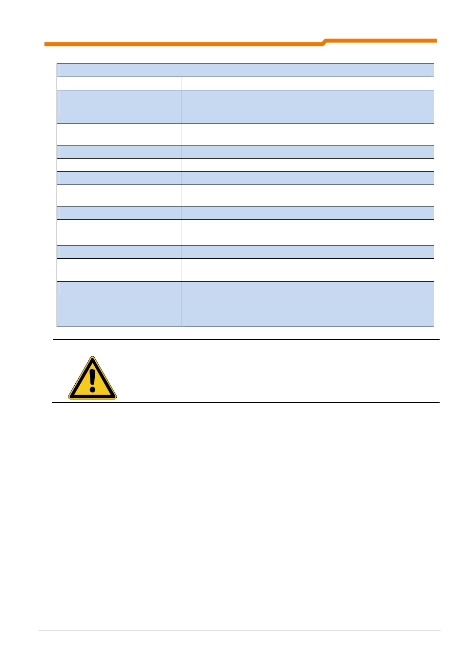
AS interface properties
Topology free
structure,
i.e. linear, tree, star, spur branches etc.
Medium for data + energy
AUX connection (black cable)
unshielded 2-wire AS interface cable (= yellow standard AS interface cable)
Insulation piercing technology as per IEC 60352-6
AUX voltage according to PELV (IEC 60364-4-41)
Length of bus cable
max. 100 m (without repeater), can be extended to 300 m with a maximum of 2
repeaters
Number of slaves
max. 31 (62 for A/B slaves)
Number of participants
up to 4 sensors and 2 actuators per slave
Addresses
Each slave is given a unique address
Messages
Messages from the master to each individual slave address with immediate
response from the slave (bidirectional)
Bit rate
4
bits (pure data) per slave and message
Cycle time
max. 5 ms for max. 31 connected S-7.4 slaves,
max. 21 ms for max. 62 connected S-7.A slaves
Error identification
Incorrect messages are reliably identified and repeated
Process data in the master
Cyclical call-up of all participants;
cyclical transfer of the data to the host or to the slaves
Master functions
Initialisation of the network, identification of the participants,
acyclic adjustment of the parameter values of the slaves,
diagnosis of the network and the AS interface slaves,
Error messages to the host, setting of the addresses for replaced slaves
NOTE
For the identification of the slave by the master, in addition to the slave address, each certified
slave has a fixed, non-volatile ID and I/O code (identification, input/output code) according to the
AS interface specification. After switching off, the ID, I/O code and the address are stored "non-
volatile" in an internal slave EEPROM. Only the slave address can be changed by the user (via
the master or a manual programming device).
3.1 Laying the bus cables
The length of the AS interface cable must not exceed 100m. For greater distances a repeater should be used.
The maximum length can be extended to 300m with two repeaters. Caution: An additional AS-i power unit
must be used after each repeater.
By the use of several repeaters in different conductors and a star configuration of the network, a total bus
length of 500m may be achieved. For this, the AS-i master must be located in the central segment of the AS-i
bus system.
In an industrial environment the correct installation of the Bus system is particularly important in order to
reduce potential interference. The following points are designed to help prevent interference and problems
right from the start. These installation instructions can not be complete and do not constitute a release from the
applicable safety and accident prevention regulations.
Although the use of shielded cable for AS interface applications is possible, it can however, have a negative
effect on the length of the conductors which can be achieved. The AS interface is a potential-free and ground
(earth)-symmetrical system, which provides a high resistance to interference in industrial environments, even
without additional measures such as shielding.
Non ground (earth)-symmetrical cable configurations over long distances are unfavourable and must be
avoided. In addition, care must be taken that the AS interface cable is laid separately from power cables.