3 led display – NORD Drivesystems BU0090 User Manual
Page 40
NORDAC AS-Interface Manual
40
BU
0090
GB
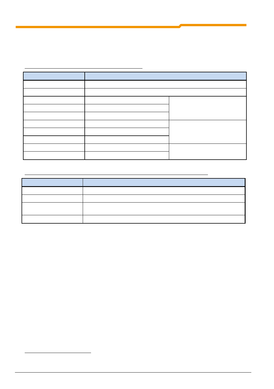
4.3 LED display
The status of the AS interface technology unit is displayed with 2 LEDs:
• Device S/E: Module status/error (dual LEDs)
• AS-Int. PWR/FLT: Standard status display for AS interface slaves (dual LEDs)
DEVICE S/E (red/green): Module status/error (dual LEDs)
Display
Meaning: AS-i / Inverter
Off
No 24V (AUX) supply voltage to the module
Yellow on
Initialisation phase of the module
Green on
AS-I communication ok
Green flashing (1s)
AS-I communication not yet active
Green, rapid flashing (0.2s)
AS-i communication timeout
3
Inverter ok
Red flashing (1s)
AS-I communication ok
Red/green, alternating (1s)
AS-I communication not yet active
Red/green, alternating (0.2s)
AS-i communication timeout
3
Inverter is in an error condition (see
frequency inverter operating
instructions)
Red, rapid flashing (0.2s)
AS-I communication ok
Red
AS-I communication timeout / not yet active
System error, e.g. plug connector not
correct or inverter off
AS-Int. PWR/FLT (red/green): Standard status display for AS interface slaves (dual LEDs)
Display
Meaning
Off
No (PWR) AS interface voltage to the module
Green on
Normal operation
Red on
No data exchange possible (possible causes: Slave address = 0, master in STOP
mode, slave not in LPS, slave with incorrect IO/ID, Reset active)
Red/green, alternating
Peripheral error (see LED: Device S/E)
In operational condition both the DEVICE S/E LED and the PWR/FLT LED illuminate green.
4.4 LED IO Display (only SK TU1-AS1 and SK TU3-AS1)
The status of the inputs and outputs of the technology unit is indicated be a total of 14 yellow LEDs (LED on
corresponds to switched on status):
• DI1-DI4
: Status of the AS interface bits, which are received by the Master.
• DO1-DO4
: Status of the AS interface bits, which are transmitted from the Master.
• IN1-IN4
: Status of digital input 1-4
• OUT1-OUT2 : Status of digital output 1-2
3
If P513 is set < 0.1, an internal timeout of 40 ms is used, which does not cause an inverter error. If P513 is set
≥
0.1, an
inverter error is reported after the elapse of the internal timeout of 40ms.