NORD Drivesystems BU0090 User Manual
Page 13
2 Modules
BU 0090 GB
13
2.2.1
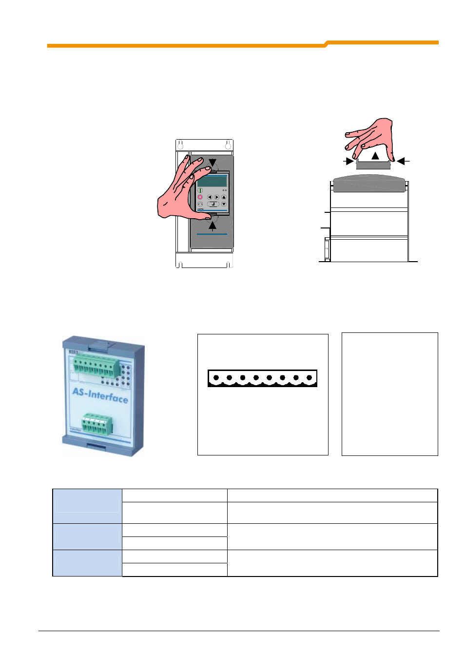
Installation of the SK TU1 technology unit
The installation of the technology units must be carried out as follows:
1. Switch off the mains voltage, observe the waiting period.
2. Remove the dummy cover by actuating the unlocking device on the top and bottom edge.
3. Allow the technology unit to engage audibly by pressing lightly on the installation surface.
2.2.2
AS interface module SK TU1-AS1
The SK 700 E supports the AS interface technology unit from software version 3.1 Rev. 1 (P707 / P742).
Device S/E
(red/green)
Module status/error. (see Section 4.3)
Status LEDs
AS-Int. PWR/FLT
(red/green)
Standard status display for AS interface slaves.
(see Section 4.3)
OUT 1 … 2
(yellow)
Digital I/O LEDs
IN 1 ... 4
(yellow)
Status of the AS interface bits received/transmitted from the
Master. (see Section 4.4)
DI 1 ... 4
(yellow)
AS-I I/O LEDs
DO 1 ... 4
(yellow)
Status at digital input/output. (see Section 4.4)
Connector 1 (I/O)
1 2 3 4 5 6 7 8
Dig In 1
Dig In 2
Dig In 3
Dig In 4
Dig Out 1
Dig Out 2
Connector 2 (PWR/AUX)
PW
R
AS
-I
(+
)
PWR A
S-I (-)
n.c.
AUX 24
V
AUX GND
700E
N O R D A C
700E
N O R D A C