3 bus structure and topology – NORD Drivesystems BU0090 User Manual
Page 25
3 Bus structure and topology
BU 0090 GB
25
3 Bus structure and topology
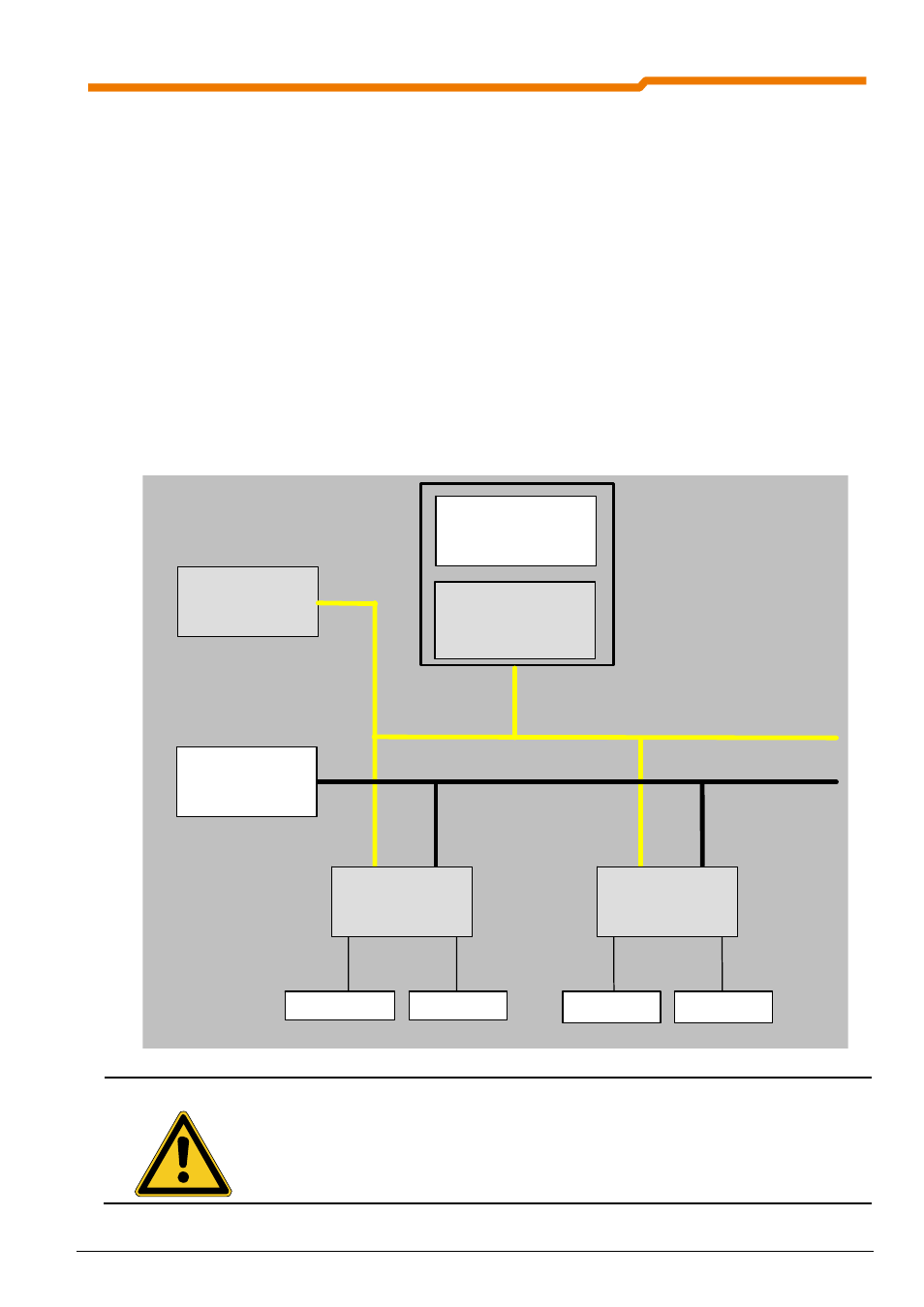
The AS interface network can be set up in any desired form. Linear, star, ring and tree structures are possible.
An existing network can be expanded by further slaves at any time. For the sake of simplicity the standard
slave application will mainly be described in this manual. Up to 31 standard slaves (i.e. a maximum of 124
binary sensors and 124 binary actuators) or 62 A/B slaves (i.e. a maximum of 248 binary sensors and 248
binary actuators) can be connected to an AS interface network or an AS interface master. Each AS interface
slave has its own address (1 to 31 (or 1A … 31A, 1B … 31B)), which is assigned to the slave with the aid of an
addressing device, or is transferred to the slave by means of a command from the AS interface master (see
the manual of the AS interface master used). Each slave address may only be assigned once.
Normally the AS interface master is a component or module of the control unit and forms the interface between
the control unit and the connected slave. An AS-i master communicates independently and exchanges data
with the connected AS-i slave options. Normal power units must not be used in the AS interface network. For
each AS interface connector, only a special AS interface power units (PELV) may be used for the power
supply. This special power supply device for the AS interface must be used in order to decouple the data in the
yellow cable. This AS interface power supply is directly connected to the yellow standard cable (ASI+ and ASI-
cable) and should be positioned as close as possible to the AS-i master in order to keep the voltage drop
small. In order to provide an adequate power supply to the NORD-AS interface modules or sensors and
actuators, an additional 24V auxiliary voltage (black cable) must be fed to each slave.
NOTE
Only separate AS interface PELV standard power units (Protection Extra Low Voltage)
with
secure separation of the low functional voltage may be used!
The PE connection of the AS interface power unit (if fitted) must always be grounded (earthed).
The brown ASI+ and the blue ASI- wire of the yellow AS interface cable must not be grounded
(earthed).
AS interface
Master
AS interface
Mains unit
PELV
Sensors
Actuators
Sensors
Actuators
24V
Mains unit for
auxiliary energy
AS interface
Slave
AS interface
Slave
PWR
AUX
PWR
AUX
AS interface
yellow cable
24 V auxiliary supply,
black cable
Control /
Automation
device