Internal status machine, Nordac as-interface manual – NORD Drivesystems BU0090 User Manual
Page 50
NORDAC AS-Interface Manual
50
BU
0090
GB
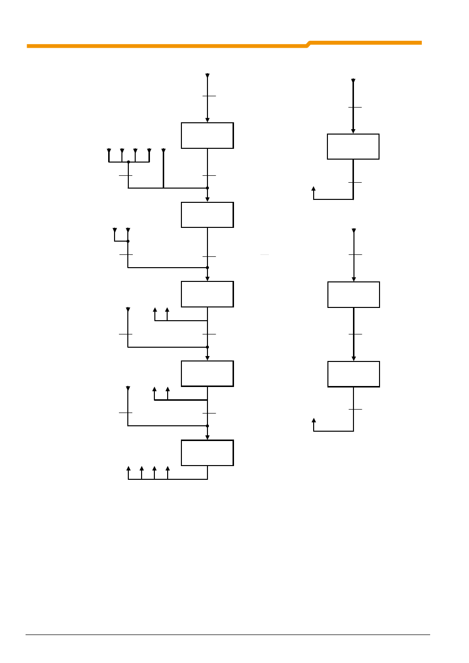
Sw itch-on
interlock
Ready for
sw itch-on
Sw itched on
Operation
enabled
Quick stop active
Error reaction
active
Error
From any device status
3
4
5
6
8
4
5
5
Not ready
for sw itch-on
Inverter sw itch-on
Loading relay activated
Error
Error reaction
completed
Bit0 = 0:
Stop
& Bit1 = 1:
voltage enabled
& Bit2 = 1:
impulse enabled
(xxxx x1xx xxxx x110)
Bit 3 = 0:
Block operation
Bit0 = 1:
sw itch on
Bit3 = 1:
operation enabled
Bit2 = 0:
Quick stop
Bit1 = 0:
Block voltage
v Bit2 = 0:
Quick stop
Priority of control com m ands:
1. Block voltage
2. Quick stop
3. Stop
4. Operation enable
5. Sw itch on
6. Operation disable
7. Reset error
Identification of statuses:
1: Bit 0 = 0
2: Bit 6 = 1
3: Bit 0 = 1
4: Bit 1 = 1
5: Bit 2 = 1
6: Bit 5 = 0
7: Bit 2 & Bit 3 = 1
8: Bit 3 = 1
3
5
2
3
3
6
4
2
2
1
2
3
7
8
f = 0 achieved
(Quick stop completed)
Bit7 0
Î
1
error acknow ledgement
Control Bits
0. Operational / Stop
1. Voltage enable / disable
2. Impulse enabled / Quick stop
3. Operation enable / disable
4. Operating condition / disable HLG
5. Enable / stop HLG
6. Setpoint enable / disable
7. Error acknow ledgement (0
Î
1)
10. Control data valid / invalid
11. Direction of rotation right
12. Direction of rotation left
14. Parameter set Bit 0
15. Parameter set Bit 1
4
5
6
Bit4 = 0:
Run dow n quick stop ramp and remain in
status ''Operation enabled''
Bit5 = 0:
Hold frequency
Bit6 = 0:
setpoint = 0%
Bit0 = 0:
Stop
5
Bit3 = 1:
operation enabled
& Bit0 = 1
: sw itch on
2
Internal status machine
2