Dwyer 2600 User Manual
Page 7
OUTPUT WIRING
Wire outputs as shown in the chart below.
Key: ‘+’ = positive; ‘-’ = negative; ‘NC’ = Normally Closed; ‘NO’ = Normally Open; ‘C’
= Common.
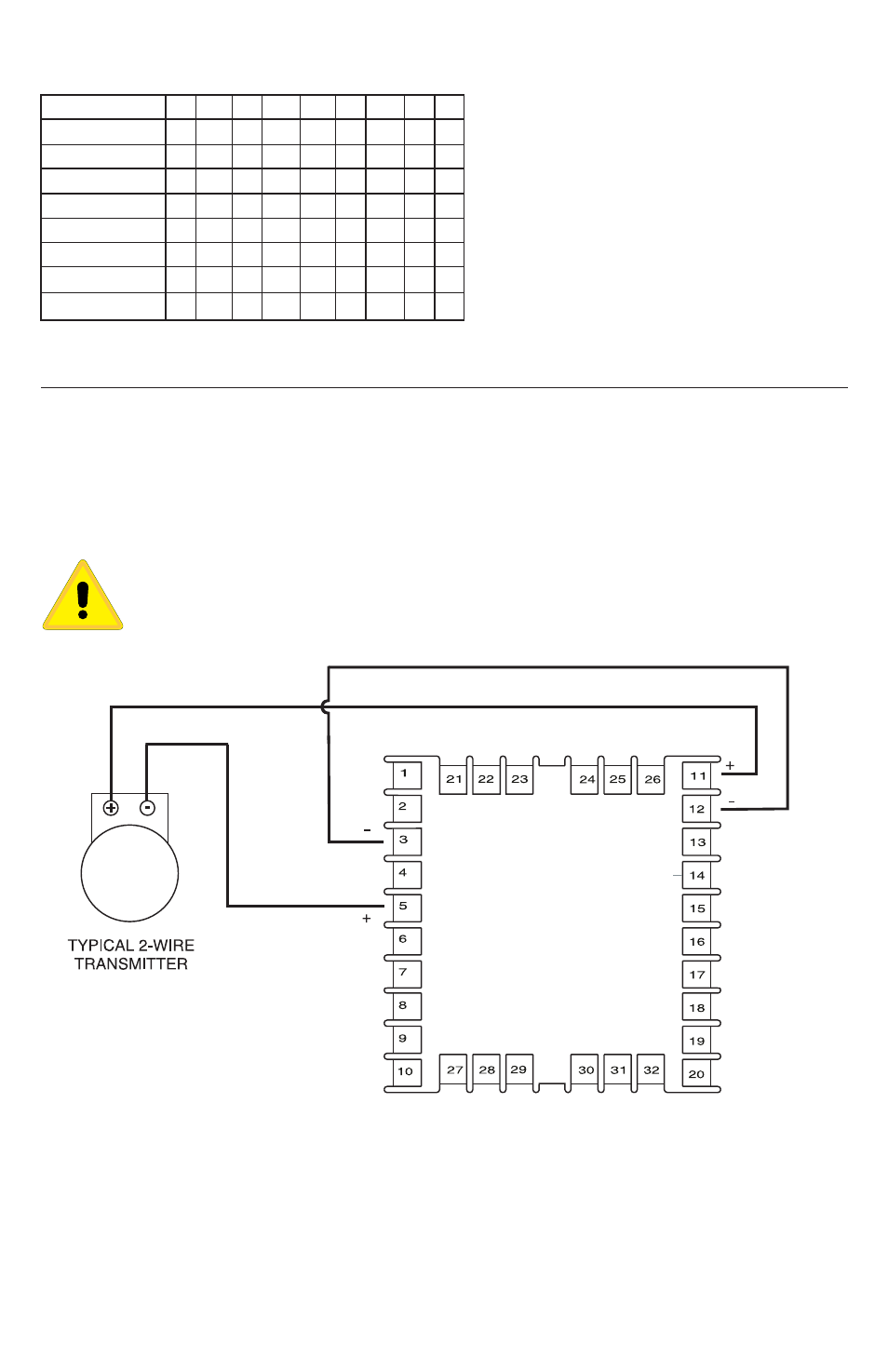
WIRING FOR 4 TO 20MA TRANSMITTER INPUTS
Wire power and outputs as shown above. Two-wire transmitters wire as shown below.
View is of instrument as seen from the rear to show wiring terminals.
For three- or four-wire transmitters follow the wiring instructions provided with your
transmitter.
CAUTION: DO NOT WIRE THE 24 VOLT POWER SUPPLY ACROSS THE
INPUT OF THE CONTROL. DAMAGE TO THE CONTROL INPUT CIRCUITRY
WILL RESULT.
May, 2013
Page 7 of 52
949-1194 Rev. 7
Terminals
SP1 SSR
SP1 15 VDC
SP1 Relay
SP1 Current
SP2 SSR
SP2 15 VDC
SP2 Relay
SP2 Current
10
+
+
13
NC
14
C
C
+
15
NO
NO
-
16
NC
17
C
C
+
18
NO
NO
-
27
-
28
-
See also other documents in the category Dwyer Sensors:
- DPMX (2 pages)
- DPMP-4 (2 pages)
- DPMP-5 (2 pages)
- DPML-4 (2 pages)
- DPML-5 (2 pages)
- DPMW (2 pages)
- MPM (36 pages)
- SPPM-HSG (1 page)
- SPPM (4 pages)
- SPPM-C (4 pages)
- A-SPPM-TC (2 pages)
- ULB (18 pages)
- CRF2 (4 pages)
- CLT (2 pages)
- PBLT2 (1 page)
- PBLTX (4 pages)
- SBLT2 (1 page)
- SBLTX (4 pages)
- MBLT (2 pages)
- FBLT (2 pages)
- ULT (8 pages)
- UTC (20 pages)
- ULTM (20 pages)
- ULSL (30 pages)
- 1500 (16 pages)
- 2500 (16 pages)
- 16A (1 page)
- 16A (44 pages)
- 1600 (36 pages)
- 1600 (8 pages)
- 8600 (40 pages)
- 8C (6 pages)
- 32B (32 pages)
- SCZ10 (20 pages)
- 8C (24 pages)
- 32A (36 pages)
- 32DZ (40 pages)
- SCD (10 pages)
- SCD-PS (2 pages)
- SCD-8 (2 pages)
- SCD-LED (2 pages)
- 650 (2 pages)
- 651 (2 pages)
- 659RTD (2 pages)