Dwyer 2600 User Manual
Page 5
INSTALLATION
Mount the instrument in a location that will not be subject to excessive temperature, shock,
or vibration. All models are designed for mounting in an enclosed panel.
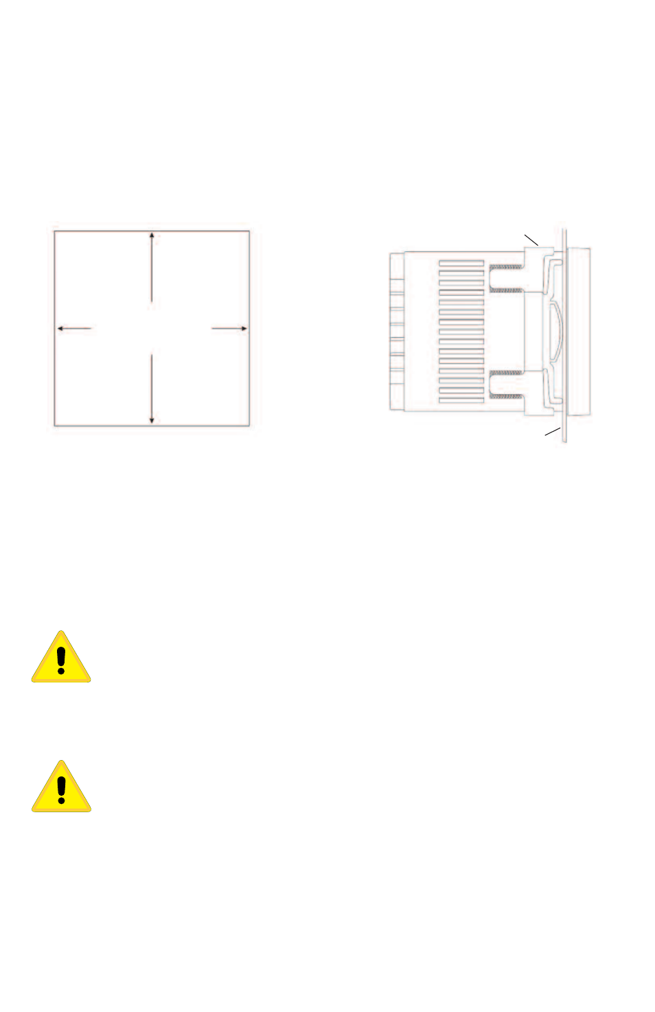
Select the position desired for the instrument on the panel. If more than one instrument is
required, maintain the minimum of spacing requirements as shown on the drawing below.
Closer spacing will structurally weaken the panel, and invalidate the IP66, UL type 4X rating
of the panel.
Prepare the panel by cutting and deburring the required opening.
From the front of the panel, slide the housing through the cut out. The housing gasket should
be against the housing flange before installing.
From the rear of the panel slide the mounting collar over the housing. Hold the housing with
one hand and using the other hand, push the collar evenly against the panel until the spring
loops are slightly compressed. The ratchets will hold the mounting collar and housing in
place.
CAUTION: It is not necessary to remove the instrument chassis from the
housing for installation. If the instrument chassis is removed from the
housing, you must follow industry standard practice for control and
protection against Electro-Static Discharge (ESD). Failure to exercise good
ESD practices may cause damage to the instrument.
WIRING
Do not run RTD, thermocouple, or other class 2 wiring in the same conduit as
power leads. Use only the type of thermocouple or RTD probe for which the
control has been programmed. Maintain separation between wiring of sensor,
optional inputs and outputs and other wiring. See the “Secure Menu” for input
selection.
For thermocouple input always use extension leads of the same type designated
for your thermocouple.
May, 2013
Page 5 of 52
949-1194 Rev. 7
92.0 mm
(3.620 in)
MOUNTING COLLAR
+0.8
-0.0
+0.032
-0.000
PANEL
PANEL CUTOUT