12 versions with integr. supply voltage 10, Ц* ь, Electrical connections – West Control Solutions KS 94 User Manual
Page 8: 12 versions with integrated supply voltage
8.12
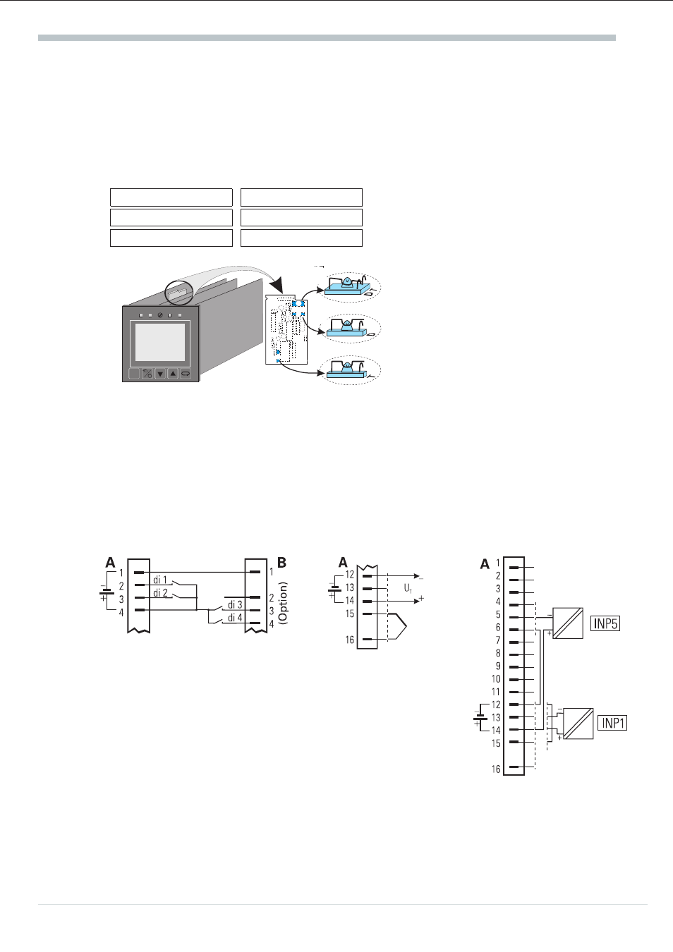
Versions with integrated supply voltage
The supply voltage can be used only for energization of a 2-wire transmitter or for energization of
max. 4 control inputs. The supply voltage is potential-free and can also be used for energizing inputs
INP3 ... INP6 or for other units. Selection of supply voltage or digital inputs is by S.I.L. switches (see
figure opposite).
Transmitter
supply voltage
Digital input
Ü
Position T
Position D
*
open
closed (D)
Ö
closed (T)
open
a
The supply voltage is only applied to terminals A12 and A14 with INP1 configured for
current or thermocouple (C.200; type) and the S.I.L. switches set for transmitter supply
(factory setting)! With the S.I.L. switches set to digital input, the voltage is applied to
terminals A1 and A4 independent of the configuration of input INP1. In this case, the voltage
input of INP5 is not available.
Electrical connections
Operating instruction KS94
10
Connection of a 2-wire
transmitter on example of
INP1 or INP5
Supply voltage for energization of
digital input (e.g. di1...di4)
External use of the supply
voltage
8.8.8.8
8.8.8.8
W2:ÀC
Y:ыыыыыо
55%
*
Ь
Ц
T
T
D
D
Ц
*
Ь