West Control Solutions KS 94 User Manual
Page 42
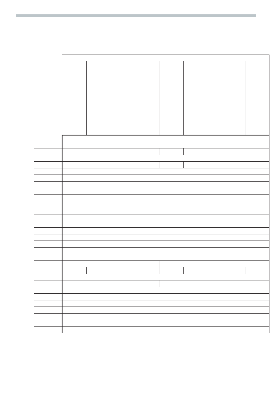
13.1
Input and output allocation with pre-configured units
The signal (e.g. X1, Y1, alarms) allocation to the inputs and outputs for the relevant pre-configuration
(factory setting) is given in the following table. Allocation can be altered at any time via front panel
or interface and should be corrected before commissioning, if necessary.
Order numbers and functions for pre-configured units
9407-92(
0;3;7)-xxx1x
Two-point
controller
(relay
output)
9407-92(
1;4;8)-xxx1x
Two-point
controller
(logic
output)
9407-92(
0;3;7)-xxx2x
Three-point
stepping
controller
9407-92(
1;4;8)-xxx2x
Three-point
stepping
controller
9407-92(
1;4;8)-xxx3x
Continuous
controller
9407-92(
1;4;8)-xxx4x
3<%-2>-point
contr.
(‘heating’
=
logic;
‘cooling’
=
relay)
9407-92(
3;7)-xxx5x
3-pnt.
stepping
controller;
3-element
controller
9407-9X(
4;8)-xxx6x
Continuous,
3-element
controller
Inputs
INP1
X1
INP3
-
X2
-
X2
INP4
-
X3
INP5
X2; Wext; Wd
Wext
X2; Wext; Wd
-
INP6
auxiliary variable ‘Z’
-
di1
W/Wext
di2
Auto/man
di3
Local / remote
di4
Programmer start / stop
di5
Programmer reset
di6
Program selection 1
di7
Program selection 2
di8
Selection parameter set 1
di9
Selection parameter set 2
di10
OVC+ (3-pnt. stepping)
di11
OVC- (3-pnt. stepping) w/dW
di12
Tracking
Outputs
OUT1
Y1
-
Y1
OUT2
-
-
Y2
Y1
-
Y2
-
OUT3
Xeff
OUT4
Alarm1
Y2
Alarm1
OUT5
Alarm2
do1
Programmer output 1
do2
Programmer output 2
do3
Programmer output 3
do4
Programmer output 4
do5
Auto/man
do6
W/Wext
Operating instruction KS94
44