9 connecting the bus interface 9, 10 connecting the inputs inp3 / inp4 9, 11 connecting the output out3 9 – West Control Solutions KS 94 User Manual
Page 7: Electrical connections
§
di10 is the input for override control OVC+ (three-point stepping).
di11 is the input for override control OVC- (three-point stepping) or the correction of the
effective set-point OFF (0) i ON (1) (configuration level C.190 / C.191).
di12 switches the bumpless transfer of the internal set-point (tracking) OFF (0) i ON (1) or
switches from set-point w (0) i w2 (1) (configuration level C.190 / C.191).
$
do5 or do6 indicates the status automatic i manual or internal i external set-point or the
status of the controller outputs Y1 / Y2 with switching controllers (configurations C.596 / C.597).
8
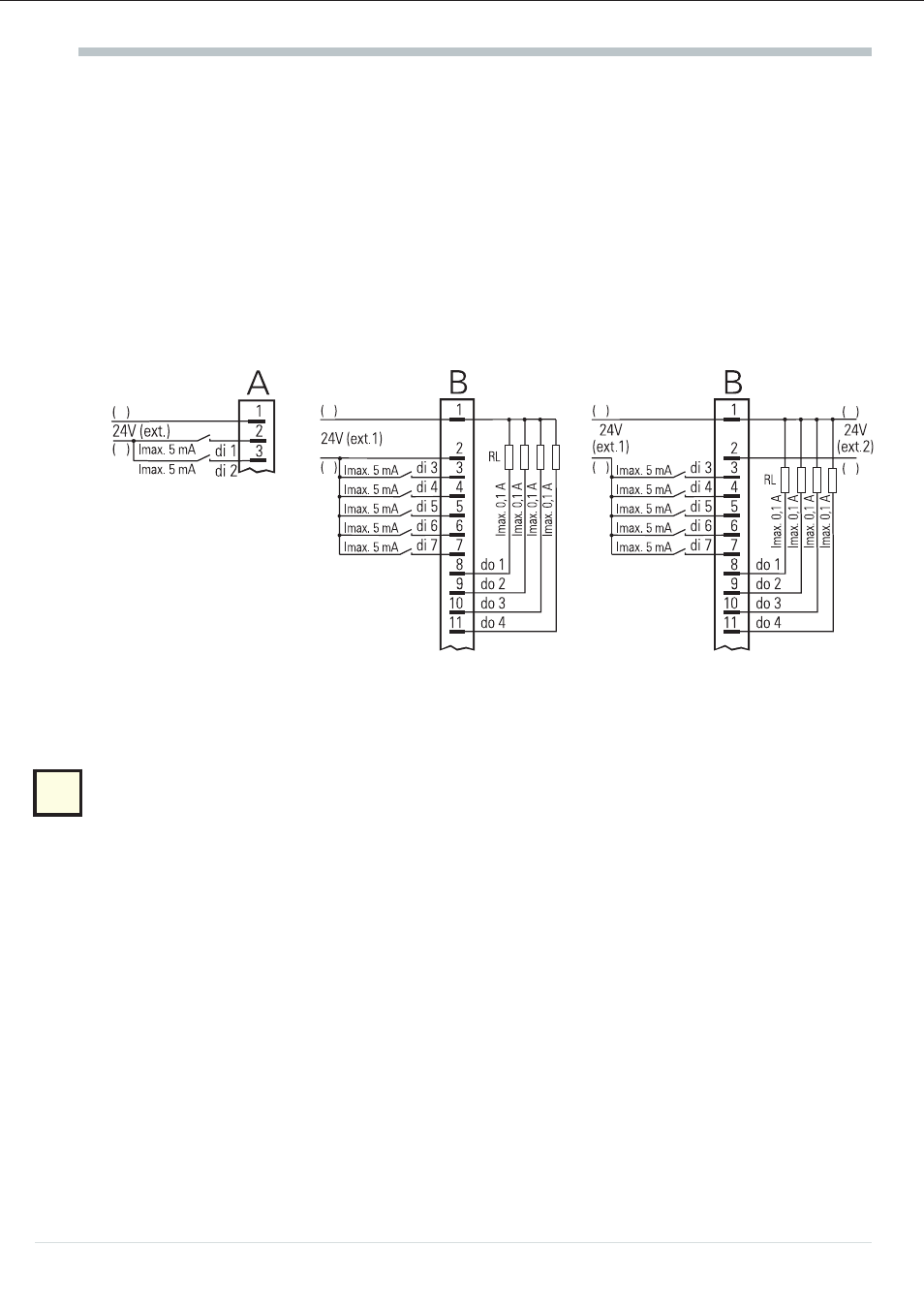
The digital inputs and outputs must be supplied from one or several external 24 V dc sources
(current consumption 5 mA/input, max. load = 0,1 A/output). Examples:
Digital inputs (connect. A)
Digital inputs and outputs with
one dc source (e.g. connector B)
Digital inputs and outputs with
two dc sources (e.g. connector B)
8.9
Connecting the bus interface !
TTL level or RS422, RS485, PROFIBUS or
I
NTER
B
US. With TTL level, an interface module for
conversion to RS422/RS485 is required. 4 units may be connected to an interface module.
8.10
Connecting the inputs INP3 / INP4 %
x3
Selectable in configuration level as e.g. process variable x2, process variable x3, auxiliary variable z,
ext. set-point or over ride control (OVC). The reference potential of the inputs is at C10.
8.11
Connecting the output OUT3 &
Depending on the version, OUT3 is a logic or continuous output (C.560). The logis signal is
0 / >20 mA (load ß600 [) or 0 / >12 V (load ?600 [). The signals are available, see page 28.
The function can be selected with configuration code C.560. By means of code C.565, the output
can be connected to a post processing (e.g. linearisation).
Electrical connections
9
Operating instruction KS94
-
+
-
+
-
+
-
+