Configuration – West Control Solutions KS 94 User Manual
Page 23
Linearization parameters:
The configuration parameters for linearization are stored as follows.
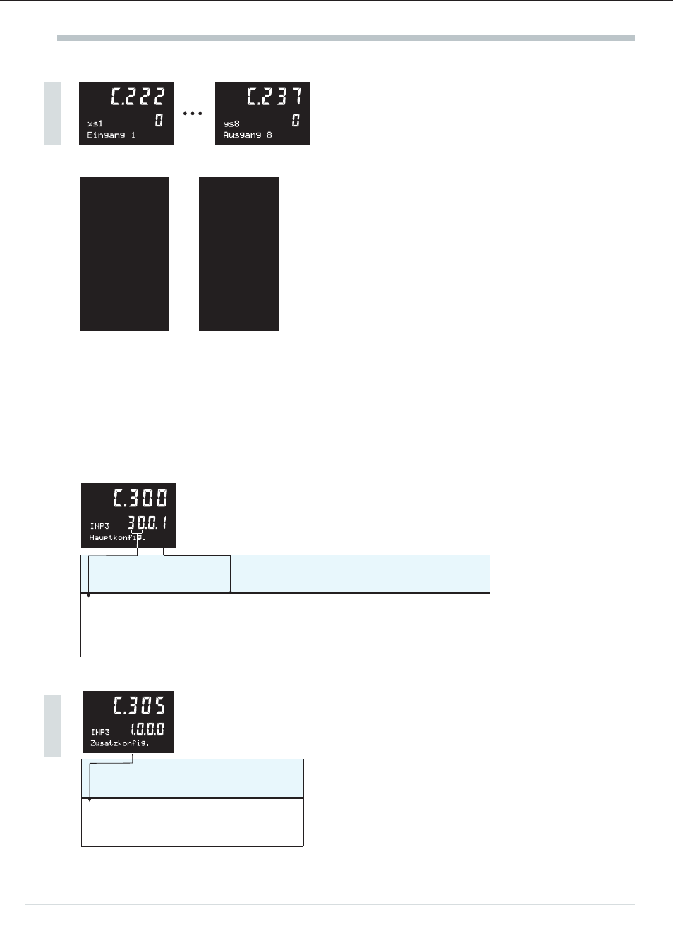
C.222 xs1
C.223 ys1
value pair 1
C.224 xs2
C.225 ys2
value pair 2
a
Note that the input values
(x-values) must be entered in
ascending order.
(xs1 C.226 xs3 C.227 ys3 value pair 3 C.228 xs4 C.229 ys4 value pair 4 C.230 xs5 C.231 ys5 value pair 5 C.232 xs6 C.233 ys6 value pair 6 C.234 xs7 C.235 ys7 value pair 7 C.236 xs8 C.237 ys8 value pair 8 The range for these configuration words is within -999 and 9999 or ‘——’ (switched off)! g For limiting the number of parameters, these functions can be used only once during pre-processing levels 1 or 2! Linearization segment points which are not required can be switched off by setting ‘——‘. 10.6.2 Signal input 3 / INP3 (ratio variable x2 or auxiliary variable z) In this case, the signal is configured for ratio variable x2 or auxiliary variable z, provided that option p.c.b. C is fitted in the controller and the function was selected during controller configuration. Main configuration: Selection is only possible with option p.c.b. C provided. Type Dp (Sensor type) (Number of digits behind the decimal point) Standard signals: 30: 0 ... 20 mA 31: 4 ... 20 mA 0: no decimal point 1: 1 digit behind the decimal point 2: 2 digits behind the decimal point 3: 3 digits behind decimal point Additional configuration: The additional configuration can be used for changing or matching the signal input default setting for the sensor type. Select only with type = 31 option p.c.b. C and ratio or auxiliary variable selected. Fail (Signal behaviour with sensor error) 1: upscale (X100) 2: downscale (X0) 3: XFail (C.313) Configuration 25 Operating instruction KS94 More More