Selection of output 1 type, 1/16-din controllers, 1/4-din and 1/8-din controllers – West Control Solutions N8100 User Manual
Page 53: Output 2 type/output 3 type
2.6
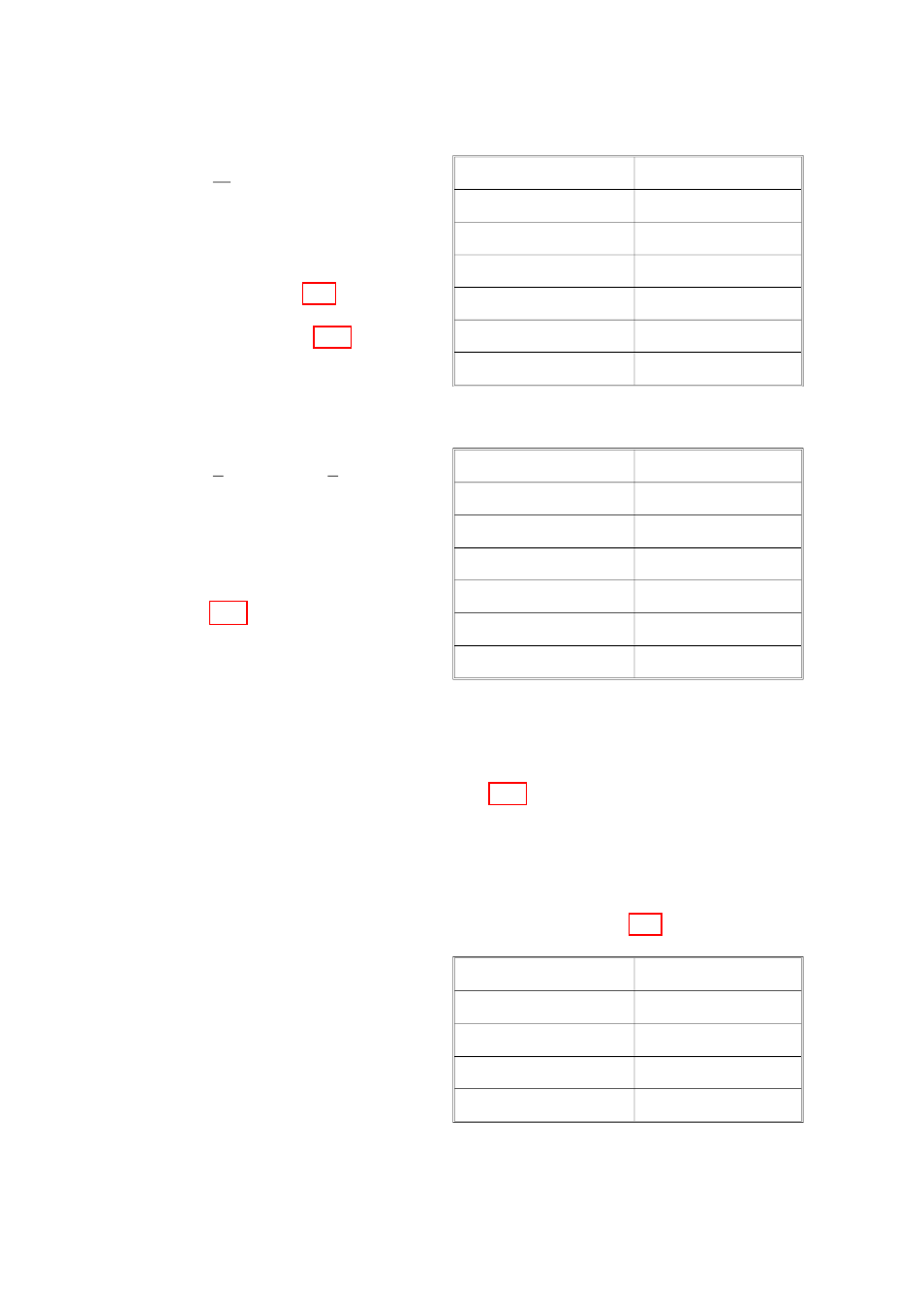
SELECTION OF OUTPUT 1 TYPE
2.6.1
1
16
-DIN Controllers
The required type of Output 1 is
selected by Link Jumpers LJ4, LJ5,
LJ6 and LJ7 on the Relay/SSR Output
1 CPU PCB (see Figure 2-4) or, on the
DC Output 1 CPU PCB, Link Jumpers
LJ8 and LJ9 (see Figure 2-5). Output
type selection is as shown on the
right.
2.6.2
1
4
-DIN and
1
8
-DIN
Controllers
The required type of Output 1 is
selected by Link Jumpers LJ4, LJ5,
LJ6, LJ7, LJ8 and LJ9 on the PSU PCB
(see Figure 2-7). Output type
selection is as shown on the right.
2.7
OUTPUT 2 TYPE/OUTPUT 3 TYPE
The type of output for Output 2 and Output 3 is determined by the Option PCB
fitted in the appropriate position (see Figure 2-1). There are four types of option
PCB which may be used for Output 2 and Output 3:
1. Relay Output Option PCB (no link jumpers)
2. Solid State Output Option PCB (no link jumpers)
3. SSR Output Option PCB (no link jumpers)
4. DC Output Option PCB (link jumpers as shown in Figure 2-8)
In the case of the DC Output Option
PCB being fitted, DC output range is
selected using link jumpers LJ8 and
LJ9, as shown on the right.
S054-2
2-5
59125
Output 1 Type
Link Jumpers Fitted
Relay or Solid State
LJ5 & LJ6
SSR Drive
LJ4 & LJ7
DC (0 - 10V)
LJ8
DC (0 - 20mA)
LJ9
DC (0 - 5V)
LJ8
DC (4 - 20mA)
LJ9
Output 1 Type
Link Jumpers Fitted
Relay or Solid State
LJ5 & LJ6
SSR Drive
LJ4 & LJ7
DC (0 - 10V)
LJ8
DC (0 - 20mA)
LJ9
DC (0 - 5V)
LJ8
DC (4 - 20mA)
LJ9
DC Output Range
Link Jumpers Fitted
DC (0 - 10V)
LJ8
DC (0 - 20mA)
LJ9
DC (0 - 5V)
LJ8
DC (4 - 20mA)
LJ9