Table 3-5. sample program (model bhk-mg 500-0.4mg), 17 calibration, 1 ieee 488 (gpib) bus protocol – KEPCO BHK-MG 200W (Full Rack) Series User Manual
Page 59: Table 3-6. ieee 488 (gpib) bus interface functions, Calibration -15, Ieee 488 (gpib) bus protocol -15, Sample program (model bhk-mg 500-0.4mg) -15, Ieee 488 (gpib) bus interface functions -15, Le 3-5), E 3-5 sho
BHK-MG (OPR) 022014
3-15
3.2.17
CALIBRATION
See Section 4.
3.3
REMOTE MODE PROGRAMMING USING SCPI COMMANDS VIA IEEE 488 (GPIB). BUS
BHK-MG Power Supplies may be programmed over a control bus using SCPI (Standard Com-
mands for Programmable Instruments). SCPI provides a common language conforming to IEEE
488.2 for instruments used in an automatic test system. The control bus used must be the IEEE
488 standard communication bus (General Purpose Interface Bus, GPIB). Refer to Table 2-1 for
input/output signal allocations.) Most power supply functions available from the keypad can be
programmed via remote commands, in addition to some that are not available from the keypad
(e.g. triggering, and local lockout).
This section includes a discussion of GPIB bus protocols (PAR. 3.3.1), instructions for changing
the GPIB address (PAR. 3.3.3), a discussion of the VISA (Virtual Instrumentation Software
Architecture) driver supplied with the unit (PAR. 3.3.5), followed by a detailed explanation of
SCPI programming (PAR. 3.5)
3.3.1
IEEE 488 (GPIB) BUS PROTOCOL
Table 3-6 defines the interface capabilities of the BHK-MG power supply (Talker/Listener) rela-
tive to the IEEE 488 (GPIB) bus (reference document ANSI/IEEE Std 488: IEEE Standard Digital
Interface for Programmable Instrumentation) communicating with a Host Computer—Controller
(Talker/Listener). Tables 3-7 and 3-8 define the messages sent to the BHK-MG, or received by
the BHK-MG, via the IEEE 488 bus in IEEE 488 command mode and IEEE 488 data mode,
respectively. These messages are enabled during the “handshake” cycle, with the BHK-MG
power supply operating as either a Talker or a Listener.
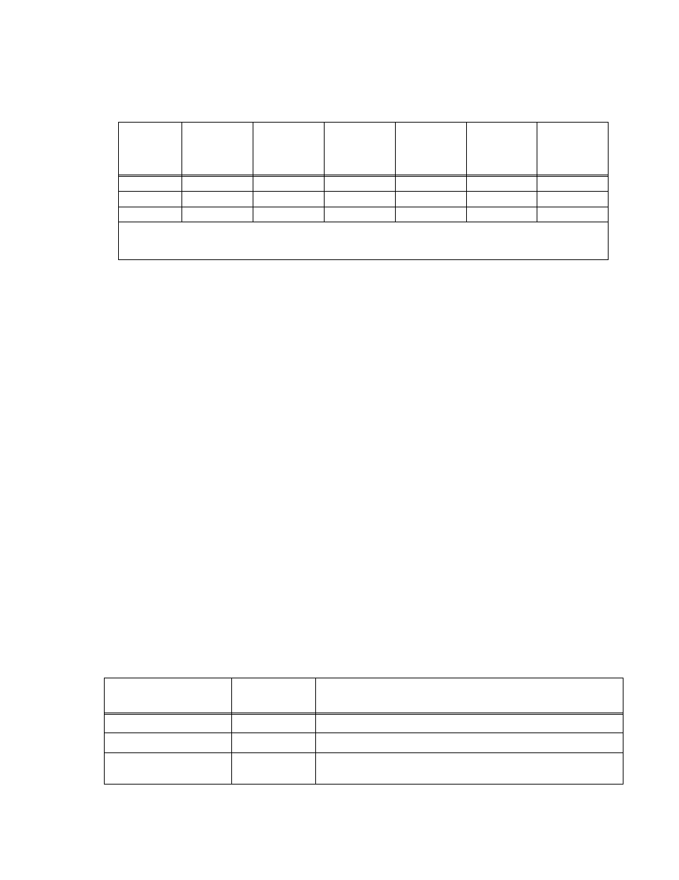
TABLE 3-5. SAMPLE PROGRAM (MODEL BHK-MG 500-0.4MG)
MEMORY
LOCATION
I SET
(Current)
(mA)
V SET
(Voltage)
(V)
OC set
(Overcurrent
Protection)
(mA)
OV set
(Overvoltage
Protection)
(V)
TIMEval
(0.01 to 655.35)
(Sec)
NEXT STEP
(Next location
to execute)
1
400
420
440
550
1.5
02
2
400
500
440
550
1.8
03
3
400
250
440
550
1.0
01
NOTE: For each cell of a program OC set and OV set must be at least 2% above the maximum values of voltage and cur-
rent expected at the load. The limit parameter (I set for voltage mode, or V set for current mode) must be at least 1%
above the maximum load current (for I set) or load voltage (for V set).
TABLE 3-6. IEEE 488 (GPIB) BUS INTERFACE FUNCTIONS
FUNCTION
SUBSET
SYMBOL
COMMENTS
Source Handshake
SH1
Complete Capability (Interface can receive multiline messages)
Acceptor Handshake
AH1
Complete Capability (Interface can receive multiline messages)
Talker
T6
Basic talker, serial poll, unaddress if MLA (My Listen Address) (one-byte
address)