Figure 3-1. lcd power on defaults, 3 error conditions, Table 3-3. error conditions – KEPCO BHK-MG 200W (Full Rack) Series User Manual
Page 49: 4 setting local mode, Error conditions -5, Setting local mode -5, Lcd power on defaults -5, 4, b.84, Re 3-1. th, R. 3.2.3 for
BHK-MG (OPR) 022014
3-5
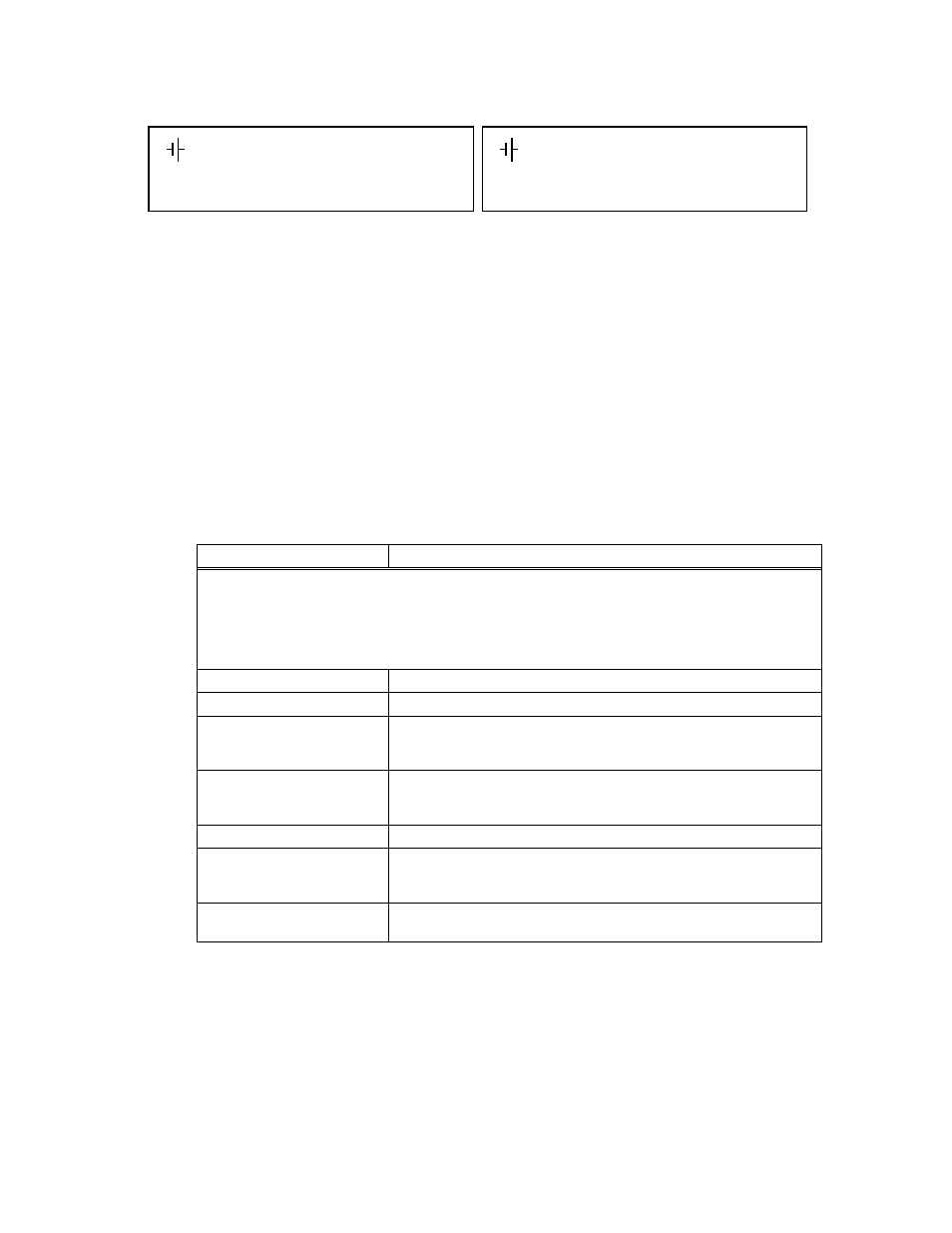
FIGURE 3-1. LCD POWER ON DEFAULTS
3.2.3
ERROR CONDITIONS
Refer to Table 3-3 for how to proceed if any of the error conditions listed appear on the LCD for
more than 90 seconds. For some errors the firmware repeats the action, and if the new attempt
is successful, the error message will be deleted and normal operation will proceed.
3.2.4
SETTING LOCAL MODE
When the power supply is turned on, it is automatically set to Local mode. If remote commands
are accepted over the GPIB bus, the power supply will automatically go into Remote mode (
Rem
at the upper left of the LCD). Pressing the LOCAL key will restore Local mode. When in Remote
mode, all keys except LOCAL are disabled.
TABLE 3-3. ERROR CONDITIONS
LCD DISPLAY SHOWS
ACTION
WARNING
When the microprocessor is not able to complete its power up
sequence, it is possible that uncontrolled high output voltage may be
present at the output. Turn off power supply immediately and discon-
nect any load. Measure the output using a voltmeter set to measure
the maximum voltage that can be delivered by the power supply.
PROM FAILS CHECK
Refer unit for service by authorized personnel.
RAM FAILS CHECK
Refer unit for service by authorized personnel.
NvRAM & Dpot Err
Restore Factory Calibration as described in PAR. 4.7, then verify that the
programmed voltage output is accurate. If problem continues, refer unit for
service by authorized personnel.
NVRAM STATUS ERROR
Restore Factory Calibration as described in PAR. 4.7, then verify that the
programmed voltage output is accurate. If problem continues, refer unit for
service by authorized personnel.
PAGE FAILS CHECK
Refer unit for service by authorized personnel.
CNFG FAILS CHECK
Restore Factory Calibration as described in PAR. 4.7, then verify that the
programmed voltage output is accurate. If problem continues, refer unit for
service by authorized personnel.
Completely blank, or a blinking
underline in the upper left corner
Refer unit for service by authorized personnel.
Loc
OFF
0.000A
0.000V
(:_:_:)
NOTE:
(:_:_:)
indicates blinking colon (:), Command Entry status
(=_=_=)
indicates blinking equal sign (=), Data Entry status
**** indicates previously set current scale. High indicates high range, Low indicates low range.
Loc
CV
0.000A
0.000V
(:_:_:)
(a) Default Display State for OUT OFF
@ Pwr-Up Selection (PAR. 3.2.7.4)
(b) Default Display State for OUT ON
at Pwr-Up Selection (PAR. 3.2.7.4)
I****
I****