4 calibration using visa driver, 1 gpib setup, Figure 4-1. gpib setup window – KEPCO BHK-MG 200W (Full Rack) Series User Manual
Page 119: 2 calibration basics, Calibration using visa driver -5, Gpib setup -5, Calibration basics -5, Gpib setup window -5
BHK-MG (OPR) (OPR) 022014
4-5
4.4
CALIBRATION USING VISA DRIVER
NOTE: The left and right single arrow buttons on the VISA panel are equivalent to the front
panel left and right arrow keys. The left double arrow button on the VISA panel is
equivalent to the 1 key on the front panel keypad; the right double arrow button is
equivalent to the 3 key.
Calibration of the BHK-MG 200W Power Supply is performed using SCPI commands imple-
mented through the Instrument driver. The driver provides a graphical interface with informa-
tional displays and prompts which lead you through the calibration of the Power Supply. This
VISA compliant driver works with many GPIB cards from suppliers like National Instruments and
Hewlett-Packard.
The following calibration procedure uses the “soft” front panel which is part of the CVI driver for
the BHK-MG 200W which can be downloaded from the Kepco website at:
www.kepcopower.com/drivers.htm
Unzip the files and doubleclick on setup.exe to install the driver.
4.4.1
GPIB SETUP
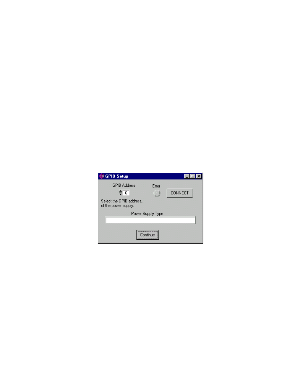
After the program is installed, double click on BHK-CTRL.exe to run the program. When the
GPIB Setup window opens (Figure 4-1), select the GPIB address of the BHK power supply to
connect to the VISA interface and click on CONNECT to open communication to the BHK-MG
via the GPIB interface. If the power supply type that appears in the GPIB Setup window is cor-
rect, click the Continue button to open the Main Panel (Figure 4-2).
FIGURE 4-1. GPIB SETUP WINDOW
4.4.2
CALIBRATION BASICS
NOTE:
Before performing calibration, set BHK for local sensing (connect +S to + OUT
terminal and connect –S to –OUT terminal at the rear panel). It is necessary to
wait 15 minutes before calibrating the unit to allow for thermal stabilization.
All adjustments are done using the four arrow buttons of the Calibration Panel (see Figure 4-3
and Table 4-1). The double arrow buttons
!
– and –
"
either increase (–
"
) or decrease
(
!
–) the output between five and 18 steps (each step is one LSB (Least Significant Bit), equiv-
alent to 0.024% of nominal value) at a time; the " and # buttons either increase (#) or
decrease (") the output one step at a time.